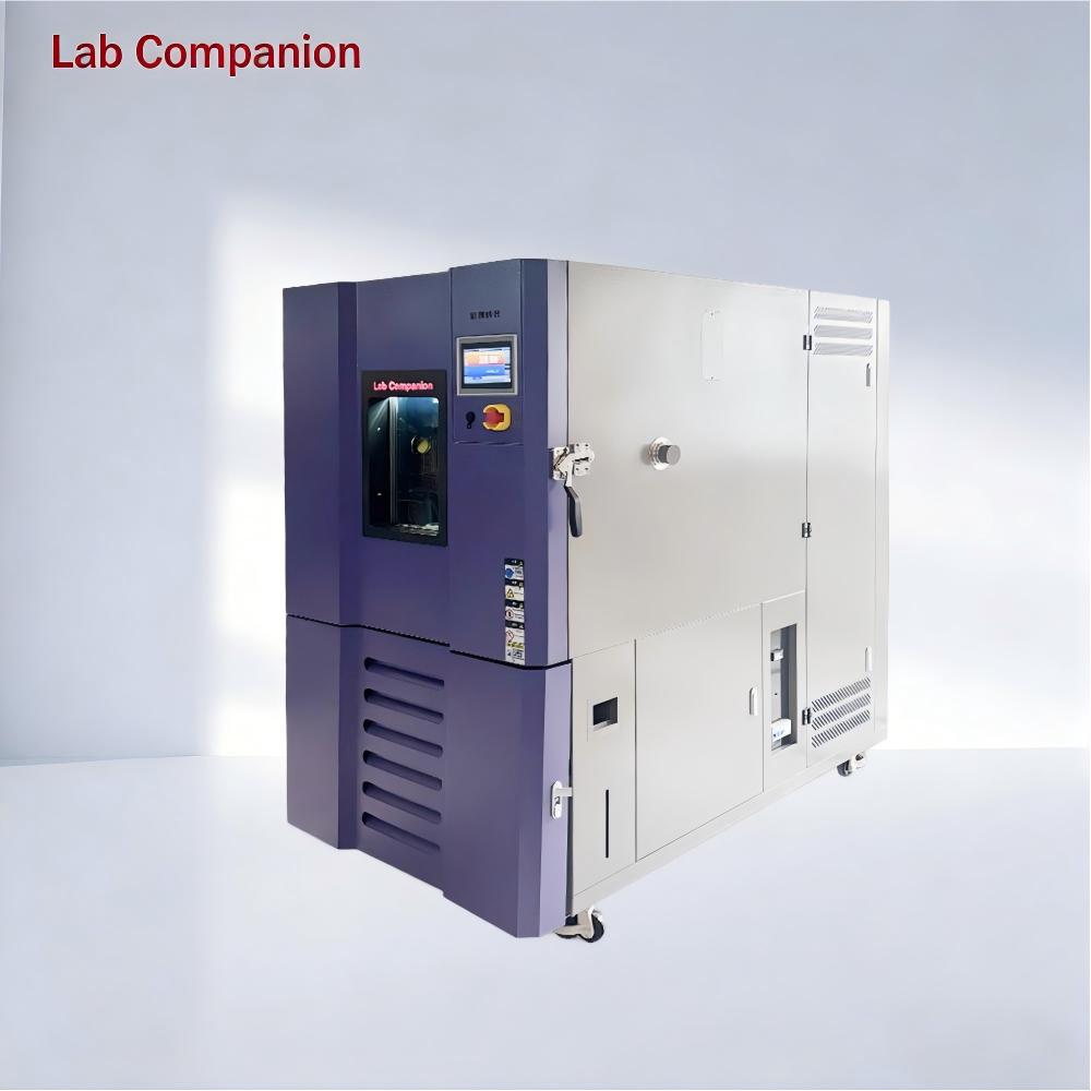
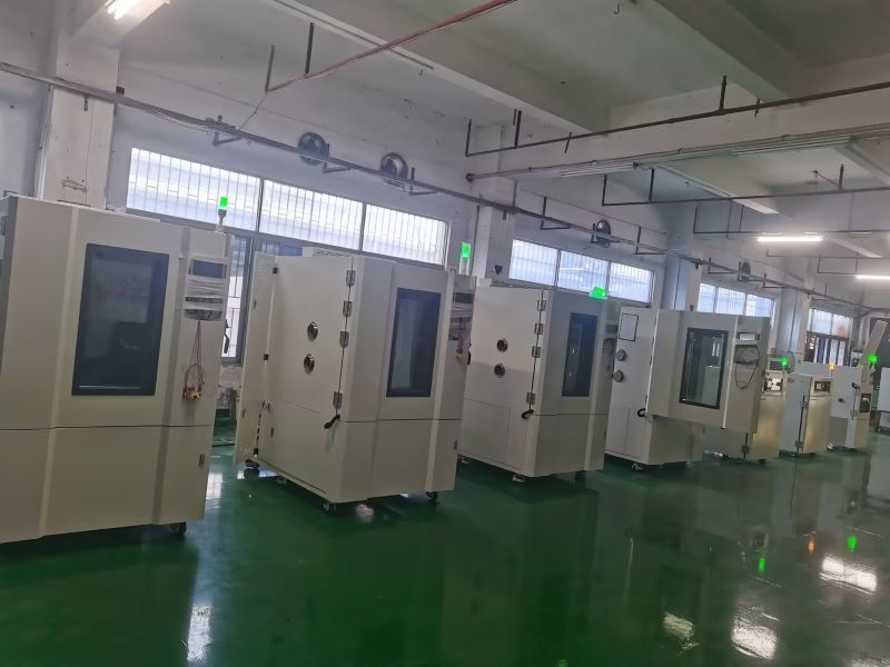
In industrial testing and scientific research, Lab Companion’s environmental test chambers are essential for product reliability verification, widely applied in electronics, automotive, aerospace, home appliances and other sectors. Both chambers focus on temperature range simulation and are easily confused in selection, yet differ sharply in core functions and application scenarios. This guide clarifies their key similarities, differences and scientific selection logic for optimal matching.
I. Key Commonalities
Both are artificial environmental simulation devices for evaluating product stability in extreme temperatures, providing data support for R&D, mass production testing and quality control, and complying with GB, IEC, ISO and other international standards.
1. Overlapping temperature range: -70℃~150℃ for high and low temperature chambers, -40℃~150℃ for constant temperature and humidity chambers, covering most industrial basic temperature test needs.
2. Unified operation & precision: Equipped with intelligent control systems (supporting parameter preset, curve programming, data export); temperature control accuracy ±0.5℃, fluctuation ≤±1℃.
II. Core Differences
The fundamental distinction is the presence of a humidity control module, which defines functional boundaries, application scenarios, structure, cost and O&M:
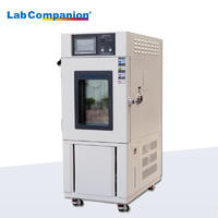
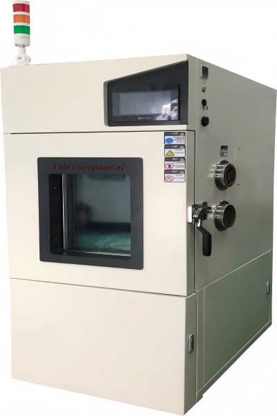
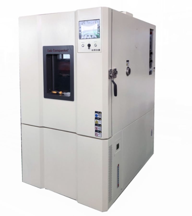
High and Low Temperature Test Chamber
1. Core Function: Only temperature regulation (heating/cooling/constant temperature), no humidity control module
2. Typical Scenarios: Temperature-only tests, e.g., high/low temperature cycle of electronic components, temperature impact of auto parts
3. Structure: Simplified configuration (heater, refrigeration system); better thermal insulation, smaller footprint for the same specification
4. Cost & O&M: Lower procurement cost; simple routine maintenance for refrigeration/heating system only, low energy consumption
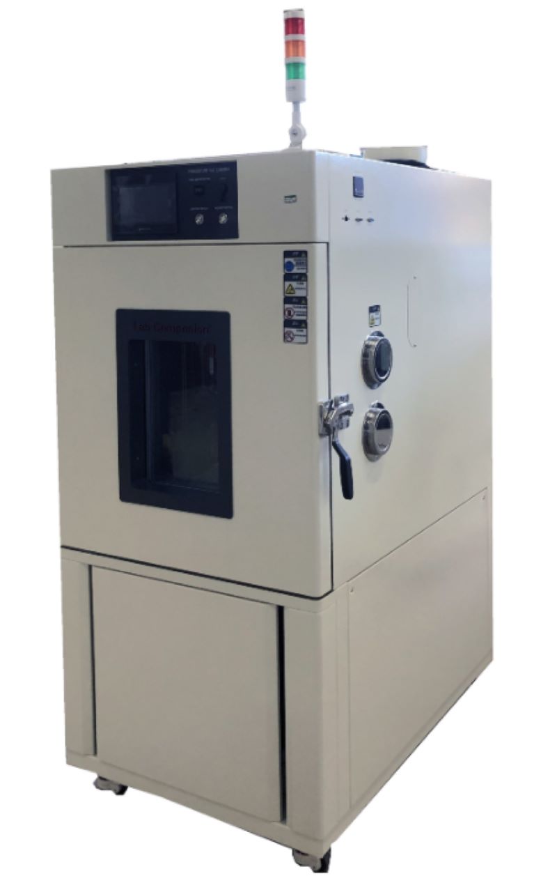
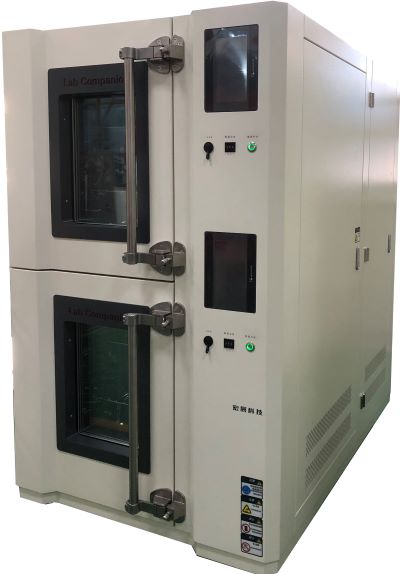
Constant Temperature and Humidity Test Chamber
1. Core Function: Dual regulation of temperature and humidity; humidity range 40%~95%RH (20%~98%RH for premium models), accuracy ±2%RH
2. Typical Scenarios: Temperature-humidity synergy tests, e.g., damp heat aging of electronics, humidity storage of medical devices, damp heat operation of home appliances
3. Structure: Complex configuration (humidification tank, dehumidifier, high-seal box); additional components for professional humidity control
4. Cost & O&M: 15%~30% higher procurement cost by specification; regular O&M for humidity parts (tank cleaning, sensor calibration), relatively higher energy consumption.
III. Selection Guide
Adhere to demand-oriented matching and balance cost performance with the following core principles:
1. Choose High and Low Temperature Test Chamber if: Only temperature change testing is needed, humidity has no impact on results, budget is limited, or laboratory space is narrow (high cost performance, easy O&M)
2. Choose Constant Temperature and Humidity Test Chamber if: Temperature-humidity synergy simulation is required, compliance with industry humidity test standards is needed, or testing moisture/corrosion-prone samples (focus on humidity parameters and reserve O&M budget)
IV. Conclusion
Lab Companion’s two test chambers both deliver stable temperature regulation for diverse industrial needs, with core differences rooted in the humidity control module. The high and low temperature chamber is ideal for basic temperature-only tests with its specialized function and cost efficiency; the constant temperature and humidity chamber excels in complex environmental simulation with its dual temperature-humidity regulation capability.
Abandon the misconception of "more functions = better". Optimal selection relies on integrating core test needs, budget, O&M capacity and laboratory space, to achieve the best balance between test effectiveness and long-term use cost. The two chambers complement each other, forming the core competitiveness of Lab Companion’s environmental test chamber series.
The key to creating a safe testing environment for the Lab high and low temperature test chamber lies in ensuring personal safety, equipment safety, test piece safety and data accuracy.
1.Personal Safety Considerations
Before opening the high-temperature chamber door to take out the sample, it is necessary to wear the high and low temperature resistant protective equipment properly. When performing operations that may cause splashing or the leakage of extremely hot/cold gases, it is recommended to wear a protective face mask or goggles.
The test chamber should be installed in a well-ventilated laboratory and avoid operating in a confined small space. High-temperature testing may release volatile substances from the test piece. Good ventilation can prevent the accumulation of harmful gases.
Ensure that the power cord specifications meet the equipment requirements and the grounding wire must be reliably connected. Most importantly, it is strictly forbidden to touch power plugs, switches and samples with wet hands to prevent electric shock.
2. Install the equipment correctly
The minimum safety distance specified by the manufacturer (usually at least 50-100 centimeters) must be left on the back, top and both sides of the equipment to ensure the normal operation of the condenser, compressor and other heat dissipation systems. Poor ventilation can cause equipment to overheat, performance decline and even fire.
It is recommended to provide a dedicated power line for the test chamber to avoid sharing the same circuit with other high-power equipment (such as air conditioners and large instruments), which may cause voltage fluctuations or tripping.
The ambient temperature for the operation of the equipment is recommended to be between 5°C and 30°C. Excessively high ambient temperatures will significantly increase the load on the compressor, leading to a decline in refrigeration efficiency and malfunctions. Please note that the equipment should not be installed in direct sunlight, near heat sources or in places with strong vibrations.
3. Ensuring the Validity and Repeatability of Tests
The samples should be placed in the central position of the working chamber inside the box. There should be sufficient space between the samples and between the samples and the box wall (it is usually recommended to be more than 50mm) to ensure smooth air circulation inside the box and uniform and stable temperature.
After conducting high-temperature and high-humidity tests (such as in a constant temperature and humidity chamber), if low-temperature tests are required, dehumidification operations should be carried out to prevent excessive ice formation inside the chamber, which could affect the performance of the equipment.
It is strictly prohibited to test flammable, explosive, highly corrosive and highly volatile substances, except for explosion-proof test chambers specially designed for this purpose. It is strictly prohibited to place dangerous goods such as alcohol and gasoline in ordinary high and low temperature chambers.
4. Safety Operation Specifications and Emergency Procedures
Before operation, check whether the box door is well sealed and whether the door lock function is normal. Check if the box is clean and free of any foreign objects. Confirm whether the set temperature curve (program) is correct.
During the test period, it is necessary to regularly check whether the operation status of the equipment is normal and whether there are any abnormal noises or alarms.
Sample handling and placement norms: Wear high and low temperature gloves properly. After opening the door, slightly turn your body to the side to avoid the heat wave hitting your face. Quickly and carefully remove the sample and place it in a safe area.
Emergency response: Be familiar with the location of the emergency stop button of the equipment or how to quickly cut off the main power supply in an emergency. Carbon dioxide fire extinguishers (suitable for electrical fires) should be provided nearby instead of water or foam fire extinguishers.
When operating a constant temperature and humidity test chamber, it is important to be aware of potential issues during the process and ensure proper operation. Improper handling can easily lead to equipment malfunctions. However, over time, some faults will inevitably occur. In this article, we will discuss several common faults and their solutions.
Fault: If the temperature does not reach the set value during high-temperature testing, the first step is to check the electrical system and troubleshoot each component. If the temperature in the constant temperature and humidity test chamber rises too slowly, check the air circulation system to ensure the adjustment damper is functioning properly. If the temperature rises too quickly, adjust the PID settings. If the temperature rises too quickly and triggers the over-temperature protection, the controller may be faulty; in this case, replace the control panel or solid-state relay.
Fault: If the constant temperature and humidity test chamber fails to meet the low-temperature test requirements, investigate whether the temperature drops very slowly or if it stabilizes at a certain point before rising again. If the temperature drops very slowly, check if the chamber was dried before the low-temperature test to maintain dryness. Ensure the samples are not placed too densely to prevent inadequate air circulation. After ruling out these issues, consider whether the refrigeration system is malfunctioning; in such cases, seek professional repair from the manufacturer.
Fault: If the constant temperature and humidity test chamber malfunctions during operation, with the control panel displaying a fault message and an audio alarm, the operator can refer to the troubleshooting section of the equipment's user manual to identify the type of fault. Professional maintenance personnel should then perform the necessary repairs to ensure the test proceeds smoothly. Other environmental experimental equipment will have other conditions in use, which need to be dealt with according to the current situation.
To achieve the desired test conditions in a constant temperature and humidity test chamber, it is inevitable to perform humidification and dehumidification operations. This article analyzes the various methods commonly used in Labcompanion constant temperature and humidity test chambers, highlighting their respective advantages, disadvantages, and recommended conditions for use.
Humidity can be expressed in many ways. For test equipment, relative humidity is the most commonly used concept. Relative humidity is defined as the ratio of the partial pressure of water vapor in the air to the saturation vapor pressure of water at the same temperature, expressed as a percentage.
From the properties of water vapor saturation pressure, it is known that the saturation pressure of water vapor is solely a function of temperature and is independent of the air pressure in which the water vapor exists. Through extensive experimentation and data organization, the relationship between water vapor saturation pressure and temperature has been established. Among these, the Goff-Gratch equation is widely adopted in engineering and metrology and is currently used by meteorological departments to compile humidity reference tables.
Humidification Process
Humidification essentially involves increasing the partial pressure of water vapor. The earliest method of humidification was to spray water onto the chamber walls, controlling the water temperature to regulate the surface saturation pressure. The water on the chamber walls forms a large surface area, through which water vapor diffuses into the chamber, increasing the relative humidity inside. This method emerged in the 1950s.
At that time, humidity control was primarily achieved using mercury contact conductivity meters for simple on-off regulation. However, this method was poorly suited for controlling the temperature of large, lag-prone water tanks, resulting in long transition processes that could not meet the demands of alternating humidity tests requiring rapid humidification. More importantly, spraying water onto the chamber walls inevitably led to water droplets falling on the test samples, causing varying degrees of contamination. Additionally, this method posed certain requirements for drainage within the chamber.
This method was soon replaced by steam humidification and shallow water pan humidification. However, it still has some advantages. Although the control transition process is lengthy, the humidity fluctuations are minimal once the system stabilizes, making it suitable for constant humidity tests. Furthermore, during the humidification process, the water vapor does not overheat, thus avoiding the addition of extra heat to the system. Additionally, when the spray water temperature is controlled to be lower than the required test temperature, the spray water can act as a dehumidifier.
Development of Humidification Methods
With the evolution of humidity testing from constant humidity to alternating humidity, there arose a need for faster humidification response capabilities. Spray humidification could no longer meet these demands, leading to the widespread adoption and development of steam humidification and shallow water pan humidification methods.
Steam Humidification
Steam humidification involves injecting steam directly into the test chamber. This method offers rapid response times and precise control over humidity levels, making it ideal for alternating humidity tests. However, it requires a reliable steam source and can introduce additional heat into the system, which may need to be compensated for in temperature-sensitive tests.
Shallow Water Pan Humidification
Shallow water pan humidification uses a heated water pan to evaporate water into the chamber. This method provides a stable and consistent humidity level and is relatively simple to implement. However, it may have slower response times compared to steam humidification and requires regular maintenance to prevent scaling and contamination.
Dehumidification Process
Dehumidification is the process of reducing the partial pressure of water vapor in the chamber. This can be achieved through cooling, adsorption, or condensation methods. Cooling dehumidification involves lowering the temperature of the chamber to condense water vapor, which is then removed. Adsorption dehumidification uses desiccants to absorb moisture from the air, while condensation dehumidification relies on cooling coils to condense and remove water vapor.
Conclusion
In summary, the choice of humidification and dehumidification methods in constant temperature and humidity test chambers depends on the specific requirements of the tests being conducted. While older methods like spray humidification have their advantages, modern techniques such as steam humidification and shallow water pan humidification offer greater control and faster response times, making them more suitable for advanced testing needs. Understanding the principles and trade-offs of each method is crucial for optimizing test chamber performance and ensuring accurate and reliable results.
Setting and Maintenance of Constant Temperature and Humidity Test Chamber
Constant temperature and humidity test chamber is a relatively precise test equipment. In order to ensure the smooth completion of each test process, the power supply of the connected equipment must be stable at around 380V to ensure that the compressor will not be damaged. In addition, you must ensure the personal safety of the personnel who receive the power, so please understand the specific operation methods before wiring.
Constant temperature and humidity test chamber adjust or replace the connected power supply. After checking that the voltage of the power supply to be connected is correct, connect the neutral terminal to the neutral terminal in the distribution chamber. Ensure that the neutral line is connected, otherwise it may cause the equipment of the constant temperature and humidity test chamber to fail to work normally or burn electrical components.
After confirming that the neutral wire is connected, connect the 3 ∮ wire to the three terminals under the main switch of the distribution chamber in the constant temperature and humidity test chamber, and tighten the screws. We need to connect the ground wire, which is connected in the same way as other power cables, and directly to the ground terminal of the distribution chamber. In the process of connecting each power cord, everyone must ensure that the different colors of the power cord can be correctly identified to avoid connection errors and normal testing.
Maintenance of constant temperature and humidity test chamber:
1, Clean the water circulation system: clean the water filter, replace the filter, check the operation of the pump, including the operation of the water flow switch, adjust the water circulation flow and test operation.
2, Check all electrical wiring and electrical components to ensure reliable operation and good contact.
3, Replace the fresh air filter.
4, Refrigeration system cleaning: replace the refrigeration oil, clean the oil filter.
5, Check the vulnerable parts of the refrigeration system: check the sealing condition of the compressor and connecting parts, and replace all filters.
6, Refrigeration system leakage inspection: check all the connecting parts of the refrigeration system and the connecting parts of the valve plate are leaked and tightened.
7, According to the working conditions to supplement refrigerant: check whether the need to supplement the system refrigerant to ensure effective cooling capacity.
8, Comprehensive system operation: check whether the operating components are in good condition.
Maintenance Method of High and Low Temperature Test Chamber
There are three common types of high and low temperature test chamber controllers: software failure, system failure and hardware failure.
1, Software failure:
Software failure mainly refers to the controller failure of the high and low temperature test chamber, including the internal parameters, the control point IS control and output signal of the solenoid valve on and off.
2, System failure:
System failure refers to the initial design problems of the refrigeration system, including the leakage of refrigerant caused by high and low temperature test chamber does not cool down, and refrigerant leakage is often due to transport and high and low temperature test chamber operation jitter or refrigeration copper pipe welding process is not fine and other reasons caused.
3, Hardware failure:
Hardware failure may lead to non-cooling hardware compressor, solenoid valve and other refrigeration components.
Then the user can listen and touch to roughly understand what is the hardware high and low temperature test chamber damage, if it is a compressor failure, the compressor sound will be abnormal or do not work does not start or the compressor itself temperature is much higher than usual temperature, and the solenoid valve failure and other refrigeration components failure users are not too good to master.
In addition, the damage of the controller and the damage of the electronic parts of the control refrigeration system may also cause the phenomenon of non-cooling and non-cooling of the high and low temperature test chamber.
Scientific principle of heating and cooling of high and low temperature test chamber:
The high and low temperature test chamber has the functions of heating, cooling, humidification and dehumidification, and can detect the product's high temperature resistance, low temperature resistance and humidity resistance. How is the temperature in the high and low temperature test chamber controlled?
The heating device is the key link to control whether the high and low temperature test chamber is heated up. The controller outputs voltage to the relay when it gets the heating instruction. The high and low temperature test chamber is about 3-12 volts of direct current added to the solid state relay. The AC end of the high and low temperature test chamber is equivalent to a wire connection, and the contactor is also drawn at the same time. Heat up the constant temperature and humidity test chamber.
Cooling is an important part of the high and low temperature test chamber, which directly affects the determination of a high and low temperature and performance, including compressor, condenser, throttling device, evaporator four major components, compressor is the heart of the refrigeration system, it inhales low temperature and low pressure gas, into high temperature and high pressure gas, through condensation into a liquid to release heat, through the fan to take away heat, Therefore, the test chamber is the reason of hot air, and then become low pressure liquid through throttling, and then become low temperature and low pressure gas through the evaporator back to the compressor, the refrigerant in the evaporator to absorb the heat of the high and low temperature chamber to complete the gasification process and absorb heat, to achieve the purpose of refrigeration, to complete the high and low temperature test chamber cooling process.
High and low temperature chamber temperature and cooling rate test procedure:
In the adjustable range of the temperature of the test chamber, the lowest nominal temperature was selected as the lowest cooling temperature, and the highest nominal temperature was selected as the highest heating temperature.
Open the cold source, so that the test chamber from room temperature to the lowest cooling temperature, stable for at least 3 hours, rise to the highest heating temperature, stable for at least 3 hours and then to the lowest cooling temperature, during the heating and cooling, record once a minute, until the end of the test process.
The principle of high and low temperature test chamber heating and cooling is so, the realization of its function is completed by the setting of the control system, understanding the principle of heating and cooling, in the use of high and low temperature test chamber must be more handy.
Composition of Electrical Components of High and Low Temperature Test Chamber
The main parts of high and low temperature test chamber are refrigeration units, condensers, evaporators, and controllers. The main parts play a key role, so everyone pays special attention to its main parts raw materials. However, most of them ignore its auxiliary parts at this time, or feel that the role of auxiliary parts is not worth noting. Few people want to count the specific parts, so it is not clear what specific electronic components are fully used in the constant temperature and humidity test chamber.
1, Refrigeration unit:
Used to control the operation of refrigeration unit, to carry out refrigeration cycle, and there are single-phase and three-phase.
2, Fan motor:
Used to control the fan circulation steam body, heat exchanger heat conduction, and there are indoor and outdoor.
3, Electric heater equipment:
Used for heating indoor air quality quality, tubular, flocculent points.
4, Timer:
Used for automatic control system timing boot.
5, DC contactor:
Used for refrigeration unit motor breaking and connection.
6, Leakage protector power switch:
It can not only connect or disconnect the main circuit like other switches, with the effect of leakage current detection and discrimination, when the main control circuit caused by power outage or cable sheath damage, leakage protection switch power supply main switch can be connected or disconnected switch components according to the identification results. It can be combined with isolation switch and heat relay to form a full-function low-voltage switching electronic device.
7, Overtemperature protection equipment:
Its role can not be ignored, when the controller temperature is not sensitive, the implementation of the E double maintenance of the box overtemperature, when the alarm is caused, the maintenance standby, the alarm will be different with the test temperature, relative change, you can further have the role of overtemperature maintenance. The basic concept is that when the total current flow of the broken wire exceeds the limit value, the temperature of the broken wire rises and the broken wire is broken. When the heat value caused by the broken wire does not exceed its short circuit capacity, the balance between the heat value and the released heat value is guaranteed, the temperature of the broken wire cannot reach the melting temperature, it is not easy to break.
Like this kind of small electronic components, in the high and low temperature test chamber looks innocuous, but for the structure of a test chamber is also very useful, without these components, a test chamber is not used, in short, the details determine the success of failure, fine without size, in the grasp of the test chamber at the same time, more should be from its key links to grasp.
Lighting Installation Position of High and Low Temperature Test Chamber
According to the different needs of users, the installation position of the lamp in the high and low temperature laboratory is different. The constant temperature and humidity test chamber tests the heat resistance, cold resistance, dry resistance and moisture resistance of various materials. Suitable for electronic, electrical, food, vehicle, metal, chemical, building materials and other industries of quality control. This series of products is suitable for aerospace products, information electronic instruments, materials, electrical, electronic products, various electronic components in high and low temperature or temperature and humidity environment, to test its various performance indicators.
The most common temperature test equipment in environmental test equipment, and similar related products are high and low temperature alternating test chamber, constant temperature and humidity test chamber, high and low temperature and humidity alternating test chamber and so on. It is suitable for high temperature and low temperature reliability test of industrial products. Walk-in high and low temperature test chamber, walk-in high and low temperature test chamber is used for thermal test of national defense industry, aerospace industry, automatic components, automotive parts, electronic and electrical parts, plastics, chemical, pharmaceutical industry and related products. It provides large parts, semi-finished products, and large temperature and humidity test environment space for finished products. It is suitable for the test equipment with large quantity and volume.
Some are installed on the interal chamber or door, and some are not installed. Where is the best place to install light bulbs?
In fact, the high and low temperature test chamber lighting has advantages and disadvantages no matter where it is installed.
If the lighting is installed in the broadcast room, you can clearly see the condition of the entire broadcast room and observe the product at any time.
The lamp is installed on the door, and when the user conducts the double 85 test or the high temperature and high humidity test, the humidity is not easy to invade the lamp, and the lamp is not easy to damage, which can greatly reduce the after-sales service fee. However, its observation field is very small, can only observe the near attractions, customers observe the product is not very convenient.
If the lamp is installed on the right side of the internal chamber, it is recommended to be completely sealed to prevent moisture intrusion to ensure the long-term stable operation of the lamp. If it is installed on a door, it is recommended that the viewing window be trapezoid, so that you can have a wider field of view.
Of course, some corporate customers choose not to install lighting when purchasing high and low temperature test chambers to reduce production costs and later management costs. However, customers can not observe products at any time when doing tests, and they can not meet the needs of different customers who want to observe products.
Sealing Problems and Solutions of High and Low Temperature Test Chamber
High and low temperature test chamber is based on the natural environment such as high temperature, ultra-low temperature, high and low temperature and low temperature drying in the room during the construction of work, and then carries out high and low temperature test and temperature and humidity aging resistance experiment on the commodity, mainly used for industrial products, such as: electronic and electrical, instrumentation equipment, cars and motorcycles, universities and other manufacturing industries.
Because of high temperature testing, ultra-low temperature testing, high and low temperature test cycle system testing, high and low temperature test and other experimental standards, high and low temperature test chamber in the high temperature standards, such as doing 150 ° C extremity of high temperature and 98% of the ambient humidity conditions, and the pressure difference between inside and outside the laboratory to expand substantially, at this moment, the sealing effect of the test chamber really matters. If the airtightness is not very good, it will cause more serious vapor leakage, affecting the precision and accuracy of the temperature.
What are the factors that cause the sealing problem of the high and low temperature test chamber?
First, the constant temperature and humidity test chamber usually has cable holes and ventilation exhaust holes, and the design scheme is very strict.
If the design scheme and production are not scientific, the gap will be too large, and the sealing of the environmental test chamber will not be good. This punching studio should also remember to plug the suitable specifications of the bottle stopper, rubber stopper, etc., to ensure that the sealing of this punching place is intact.
Second, the problem of sealing rubber strips of high and low temperature test chamber. We usually ignore this problem, feel that the sealing strip is added to the door hinge, and should be very sealable under the inhibition of the door hinge, because the aging of the silicone seal, the selection of hard flexibility is unscientific, and the sealing strip is fixed and not the same, often causing steam leakage. It is also simple to handle, often test its tightness, and find that the embrittlement of the sealing strip must be replaced as soon as possible.
Third, because the general volume of the high and low temperature test chamber is relatively large, the tail door specifications are expanded, and the net weight is very large, and the vertical orientation of the door hinge is offset after the long-term load, and the tail door is shifted and closed. Such problems are usually dealt with according to the modified high-load door hinges and the total number of door hinges.
From the above analysis, it can be seen that the sealing problem of the high and low temperature test chamber has some design problems and some maintenance problems. Therefore, we should strictly follow the equipment maintenance manual for regular maintenance in the use of equipment to ensure the normal operation of equipment and no deviation of technical parameters.
Principles That Operating Constant Temperature and Humidity Test Chamber Should Follow
Constant temperature and humidity test chamber, also known as constant temperature and humidity test machine, programmable temperature and humidity alternating test chamber, thermostat or constant temperature and humidity chamber, can be used to test various environments and test equipment material performance, this material has heat resistance, cold resistance, dry resistance and humidity resistance. However, when using the constant temperature and humidity test chamber, the correct operation helps to obtain scientific data for the experimenter, so what principles should be followed in the operation of the constant temperature and humidity test chamber?
First, in the environmental test, the operator must be familiar with the required test sample performance, test conditions, test procedures and test technology, familiar with the technical performance of the test equipment used, and understand the structure of the equipment, especially familiar with the control operation and performance. At the same time, read the operation manual of the test equipment carefully to avoid abnormal operation of the test equipment due to operation errors, which may cause damage to the test sample and incorrect test data.
Second, in order to ensure the normal operation of the test, appropriate testing equipment should be selected according to the different conditions of the test sample, and a reasonable proportion between the temperature and humidity of the test sample and the effective volume of the laboratory should be maintained. For tests of heated test samples, the volume should not be greater than one-tenth of the effective volume of the test chamber. The volume of the unheated test sample should not exceed one-fifth of the effective volume of the test chamber.
Third, for environmental tests that need to add media to the test, it should be correctly added according to the test requirements. For example, there are certain requirements for water in temperature and humidity test chambers and the resistance should be reduced. There is a more economical and convenient form of pure water on the market. Its resistance is equivalent to distilled water.
Fourth, wet bulb gauze (wet bulb paper) has certain requirements for use in a temperature and humidity test chamber, and no gauze can be replaced, because the relative humidity reading is the difference between the root distance and temperature and humidity, and strictly speaking, it is also related to the local atmospheric pressure and wind speed at the time. The indicator value of wet-bulb temperature is related to the amount of water absorbed by the gauze and the amount of surface evaporation. These are directly related to the quality of the gauze, so the weather stipulates that the wet ball gauze must be a special "wet ball gauze" woven from linen. Otherwise, it is difficult to ensure the correctness of the wet bulb thermometer value, that is, the correctness of the humidity. In addition, the position of the wet gauze is also clearly specified. Gauze length: 100mm, tightly wrap the sensor probe, probe 25-30mm away from the humidity cup, gauze immersed in the cup to ensure the accuracy of equipment control and humidity.
Fifth, the location of the test sample should be more than 10 cm away from the wall of the chamber, and multiple samples should be placed on the same plane as far as possible. Samples should be placed without blocking air outlets and return vents, and temperature and humidity sensors should be kept at a distance. Make sure the test temperature is correct.
Operating the constant temperature and humidity test chamber in accordance with the above principles, the correct operation of the test process will greatly improve the level of test data. As long as the above principles are adhered to, it should be said that the temperature and humidity tests can be successfully performed.
Introduction and Comparison of Thermocouple Temperature Sensing Lines
Instructions:
The background principle of thermocouple is "seebeck effect", also known as the thermoelectric effect, the phenomenon is that when two different metal endpoints are connected to form a closed loop, and if there is a temperature difference between the two endpoints, then there will be current generated between the loops, and the higher temperature contact in the loop is called "hot junction". This point is usually placed at the temperature measurement; The lower end of the temperature is called "cold junction", that is, the output end of the thermocouple, whose output signal is: DC voltage is converted into a digital signal through the A/D converter and converted into the actual temperature value through the softwares algorithm.
Various electric heating couples and their range of use(ASTM E 230 T/C):
type E
type J
type K
-100℃ to 1000℃±0.5℃
0℃ to 760℃±0.1℃
0℃ to 1370℃±0.7℃
Brown (skin color)+ purple - red
Brown (skin color)+ white - red
Brown (skin color)+ yellow - red
JIS,ANSI(ASTM) thermoelectric coupling appearance identification:
Thermoelectric coupling
JIS
ANSI(ASTM)
Rind
Positive end
Negative end
Rind
Positive end
Negative end
B type
Grayish
Red
white
Grayish
Grayish
Red
R,S type
Brown
Red
white
Green
Brown
Red
K,W,V type
Green
Red
white
Yellow
Yellow
Red
E type
Purple
Red
white
Purple
Purple
Red
J type
Yellow
Red
white
Brown
white
Red
T type
Tawny
Red
white
Green
Green
Red
Note:
1.ASTM, ANSI: American standard
2.JIS: Japanese standard


 Get A Quote


 IPv6 network supported