banner
Home blog

HUMIDITY & TEMPERATURE TEST CHAMBER OPERATIONAL GUIDELINES

HUMIDITY & TEMPERATURE TEST CHAMBER OPERATIONAL GUIDELINES

March 19, 2025

1.Equipment Overview

The Humidity & Temperature Test Chamber, also known as an Environmental Simulation Testing Apparatus, is a precision instrument requiring strict adherence to operational protocols. As a Class II electrical device compliant with IEC 61010-1 safety standards, its reliability (±0.5°C temperature stability), precision (±2% RH humidity accuracy), and operational stability are critical for obtaining ISO/IEC 17025 compliant test results.

2.Pre-Operation Safety Protocols

2.1 Electrical Requirements

  •  Power supply: 220V AC ±10%, 50/60Hz with independent grounding (ground resistance ≤4Ω)
  •  Install emergency stop circuit and overcurrent protection (recommended 125% of rated current)
  •  Implement RCD (Residual Current Device) with tripping current ≤30mA

2.2 Installation Specifications

  •  Clearance requirements:

       Rear: ≥500mm

       Lateral: ≥300mm

       Vertical: ≥800mm

  •  Ambient conditions:

      Temperature: 15-35°C

      Humidity: ≤85% RH (non-condensing)

      Atmospheric pressure: 86-106kPa
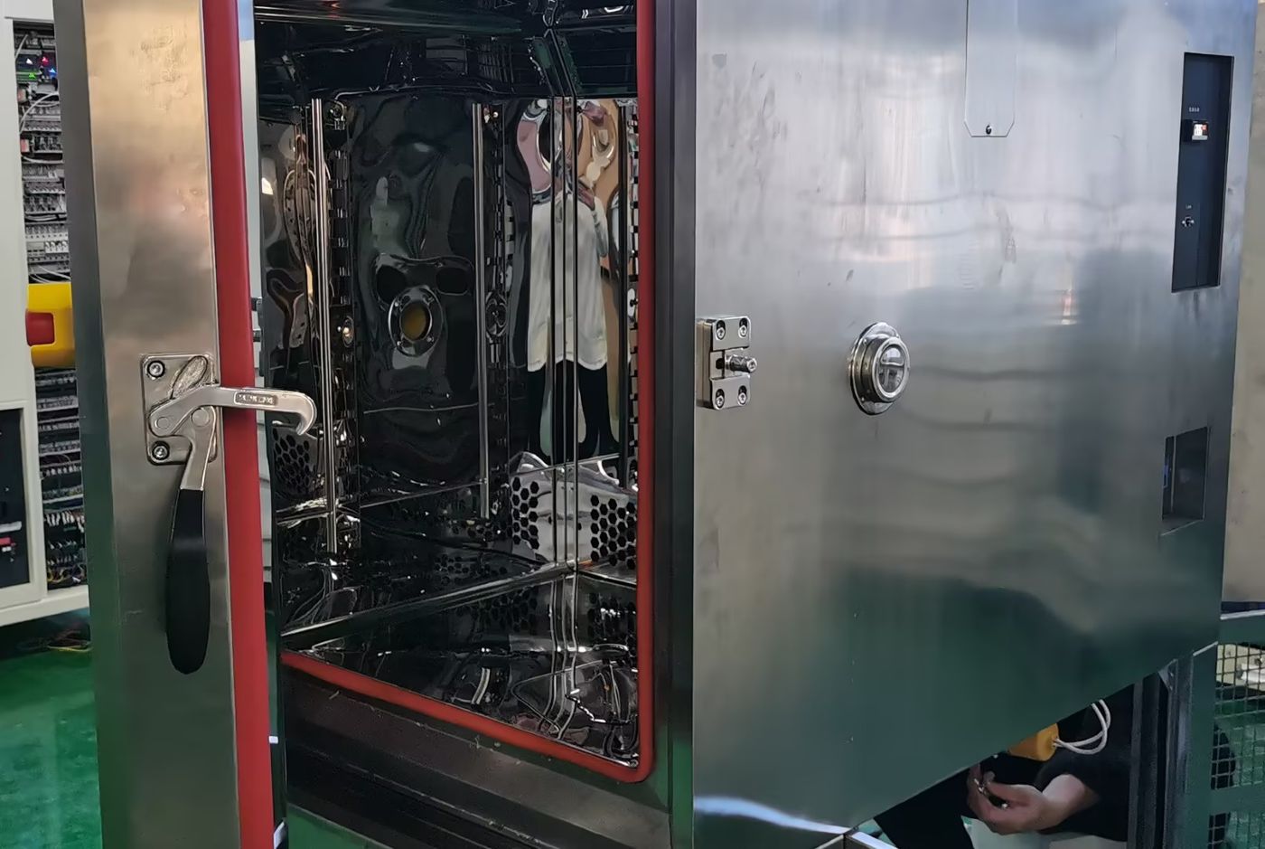
 

Stainless steel Humidity & Temperature Test Chamber


3.Operational Constraints

3.1 Prohibited Environments

  •  Explosive atmospheres (ATEX Zone 0/20 prohibited)
  •  Corrosive environments (HCl concentration >1ppm)
  •  High particulate areas (PM2.5 >150μg/m³)
  • Strong electromagnetic fields (>3V/m at 10kHz-30MHz)

4.Commissioning Procedures

4.1 Pre-Start Checklist

  •  Verify chamber integrity (structural deformation ≤0.2mm/m)
  •  Confirm PT100 sensor calibration validity (NIST traceable)
  •  Check refrigerant levels (R404A ≥85% of nominal charge)
  •  Validate drainage system slope (≥3° gradient)

5.Operational Guidelines

5.1 Parameter Setting

  •  Temperature range: -70°C to +150°C (gradient ≤3°C/min)
  •  Humidity range: 20% RH to 98% RH (dew point monitoring required >85% RH)
  •  Program steps: ≤120 segments with ramp soak control 

5.2 Safety Interlocks

  •  Door-open shutdown (activation within 0.5s)
  •  Over-temperature protection (dual redundant sensors)
  •  Humidity sensor failure detection (auto-dry mode activation)

6.Maintenance Protocol

6.1 Daily Maintenance

  •  Condenser coil cleaning (compressed air 0.3-0.5MPa)
  •  Water resistivity check (≥1MΩ·cm)
  •  Door seal inspection (leak rate ≤0.5% vol/h) 

6.2 Periodic Maintenance

  •  Compressor oil analysis (every 2,000 hours)
  •  Refrigerant circuit pressure test (annual)
  •  Calibration cycle:

        Temperature: ±0.3°C (annual)

        Humidity: ±1.5% RH (biannual)

7.Failure Response Matrix

Symptom Priority Priority Immediate Action Technical Response
Uncontrolled heating P1 Activate emergency stop Check SSR operation (Vf <1.5V)
Humidity oscillation P2 Initiate auto-dry cycle Verify dew point sensor calibration
Condenser frost P3 Reduce humidity setpoint Check expansion valve (ΔT 5-8°C)
Water level alarm P2 Refill with DI water Conduct float switch resistance test

8.Decommissioning & Disposal

  •  Refrigerant recovery per EPA 608 regulations
  •  PCB disposal compliant with RoHS Directive 2011/65/EU
  •  Steel components recycling (≥95% recovery rate)

9.Compliance Standards

  •  Safety: UL 61010-2-011, EN 60204-1
  •  EMC: FCC Part 15 Subpart B, EN 55011
  •  Performance: ASTM D4332, IEC 60068-3-5


leave a message

leave a message
If you are interested in our products and want to know more details,please leave a message here,we will reply you as soon as we can.
submit

home

products

WhatsApp

contact us