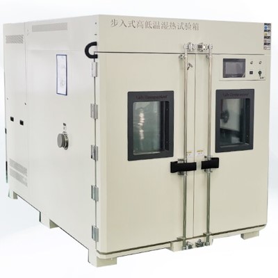
ER-135MHP-W, Step in constant temperature and humidity bath, constant temperature and humidity chamber style book (water-cooled)
Project
Type
Form
ER - 135MHP-W
Nature
ability
*1
*2
Temperature and humidity mode
The way of wet ball
Temperature and humidity model * 3
-40~+ 80 ℃ /10~95%RH
Temperature and humidity electrode amplitude
± 0.3 ℃ / ± 2.5%RH
Temperature and humidity distribution
± 0.75 ℃ / ± 5.0%RH
The temperature drops the time
+20~ -40 ℃ Within 170 minutes
Temperature rise time
+20~+ 80 ℃ Within 50 minutes
Noise value
*6
Room outside
65dB
Indoor side
79B
Statutory freezing capacity ( 50 / 60Hz )
2.57/2.81
Product shape-inch method (width, depth and height)
Please refer to the configuration diagram
Warehouse board laboratory
Bed area
13 . 0 m2
The shape of inch method
*7
Wide
3600mm
Deep
3600mm
High
2325mm
Have oneself
Intensification method
*7
Wide
3450mm
Deep
3450mm
High
2100mm
External materials
Ivory painted steel plate
Inside the material
Stainless steel plate (SUS304)
Broken heat material
Hard synthetic resin
The weight resistance of the board
5.9 k N/ m2 {600 kgf / m2 }
Door (width and height)
830 mm × 1800 mm Single piece open
Measurement (width and height)
190 mm × 320 mm The door
Indoor light capacity (quantity)
60W( 2 individual )
Cable hole
φ 50 1 (500mm from bed surface height, 1 side)
Controller model and shape method
Wide, deep and high
EU - 6 5MH*2 unit 1200 mm × 710 mm × 1940 mm
External outfit
Indoor
stainless steel sheet and plate (SUS304)
Outdoor
L coating color on steel plate; ivory color: color table mark 2.5Y8/2 )
Operate
Steel plate coating color; ivory color: color table mark2.5Y8/2
The oneself can shrink machine
Cooling medium
R404A
Output of freezer 1 (staff)
2.2kW(1) × 2
Cooling and dehumidifier
Multi-channel mixed heat sink type
Condenser (staff number)
Transverse fin type (2) 2
Calorifier
Form
Nickel-chromium heat-resistant alloy heater
Volume
5 . 7kW(3 φ 200V) × 2
Humidifier
Form
SUS 316L Make a surface steam type humidifier
Volume
5 . 4kW(3 φ 200V) × 2
Air supply device
Form (quantity)
Single air supply multi-blade air fan (1)
Survival outside the machine
0 Pa{ 0 mmAq}
Blowing rate
25 (m3 / min )
Back to the uterus
1100( r / min )
Motor form
VTFO-K
Motor output (pole number)
0.75kW(6) × 2
Moisturizing water supply
installation
The water supply cylinder
Water quality * 8
Electrical conductivity is below 10 μ S / cm
Volume
4L × 2
Feedwater
way
Moisturizing disk
gravity type
Wet ball Wick disc
Electromagnetic valve type
Controller
The temperature is set
-42.0 ~+ 82.0 ℃
Humidity is set
0~98% RH ( Dry Bulb Temperature 10 ℃ ~ 80 ℃ )
Time setting Fanny
0 ~ 999 Time 59 points (programmed type)0 ~ 20000 Time 59 points (value)
Set decomposition energy
Temperature 0.1 ℃ , humidity 1% RH , time 1 minute
Indicate accuracy
Temperature ± 0.8 ℃ ( typ. ), humidity ± 1% RH ( typ. ), time ± 100 PPM
Vacation type
Value or program
Stage number
20 stage / 1 form
The number of procedures
Number of incoming force (RAM) programs, maximum 32 programs / internal ROM programs, maximum 13 programs
Round-trip number
Maximum of 98 or unlimited
Number of round-trip repeats
Maximum 3 time
Displace the end
JP t 100Ω (a t 0 ℃ ), grade B(JIS C1604-1997 )
control action
When splitting the PID action
Endovirus function
Early delivery function, standby function, setting value maintenance function, power outage protection function,
Power action selection function, maintenance function, transportation round-trip function,
Time delivery function, time signal output function, overrising and overcooling prevention function,
Abnormal representation function, external alarm output function, setting paradigm representation function,
Transport type selection function, the calculation time represents the function, the slot lamp lamp function
Project
Type
Form
ER - 55MHP-W
Temperature control machine
Control panel
Equipment machine
Color LCD operating panel (force contact mode),
Represents the lamp (power supply, transport, abnormal), test material power supply system royal terminal,
External alarm terminal, time signal output terminal, power cord connector,
Protective device
Warehouse plate test uterine cavity
Test material with
Temperature rise overcooling prevention function (microcomputer: automatic setting)
Temperature rise ter (set: Set above 60℃)
Refrigerating cycle
Overload protection device, high blocking device
Calorifier
Temperature over-rise protection device, temperature fuse
Humidifier
Air burning prevention device (2 weight), wet plate water level regulator
Blower
Overload protection device
Control panel
Leakage breaker for power supply, fuse (for heater, humidifier),
Fuse (for operating loop), fan reverse prevention relay
In addition to control
Frost system
Defrosting method * 5
Stop cycling defrosting (freezer transport stop),
Heat up defrosting
Cold control
But the system
water
Concondensation control mode (quantity)
Water-making valve for cooling water (2) 2
Repeat
measure
Therstat (operated)
300kg × 2
Electricity
Endyceps sinensis
particular
nature
Source
Communication three phases 380V 50Hz
Maximum load current
45A × 2
The power supply uses a leakage breaker
60A ( Sensory current 30mA) × 2
Power distribution
Rubber insulation hose 22m m2 × 2
Coarseness of grounding wire
5.5m m2 × 2
cold
step back
water
*9
Water yield;the yield of water
40L / min ( inlet water temperature 32 ℃ ) × 2
Water pressure
0.1~0.5M Pa{ 1.0~5.0 kgf / cm2 }
water temperature
18~ 32 ℃
Pipe-inch method
Inlet / exit
PT 1 parent seat / PT 1 parent seat
Humidifying water supply pipe distribution inch method * 8
PT 1 / 2 parent seat
arrange
water
Pipe-inch method
drain-pipe
PT 1 / 2 parent seat
Its
Product products (staff)
reduce pressure(1) * 8
Wet ball wick (15)
Take instructions (1)
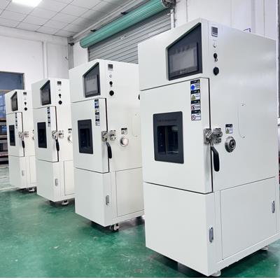
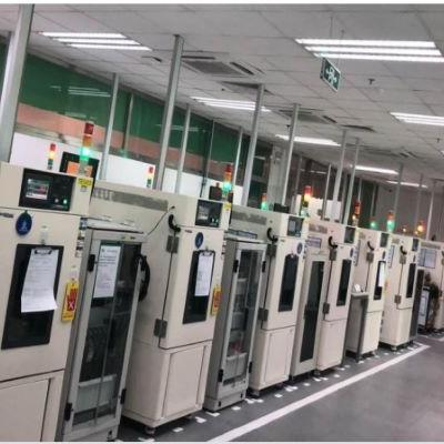
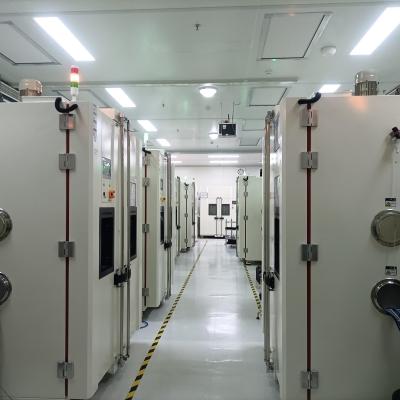
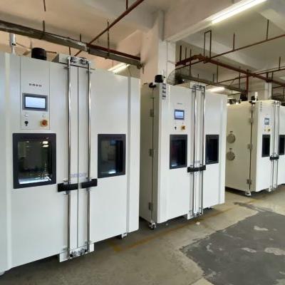
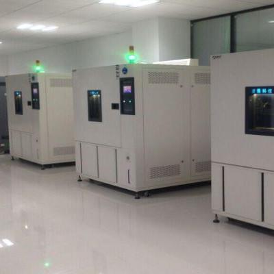
Large volume vertical temperature shock test chamber
By alternating the movement of the test specimen between the cold chamber and the hot chamber, the temperature shock test chamber can apply a very, very fast rate of temperature change to the test specimen, which can expose possible defects and also be used to define the service life of the test specimen.
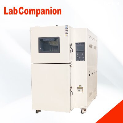
The temperature shock test chamber of Lab Companion TS-2 model is mainly used for heavy loads. Due to its compact structure and small footprint, it is particularly recommended for use in production lines.
Lab Companion has a research institution specializing in the development of environmental testing equipment, with mature environmental testing research methods and laboratories. It has gathered a group of excellent talents and well-known experts in the industry, and a strong R&D team leads the development direction of domestic environmental testing technology. Currently, the company has independent intellectual property rights for environmental testing equipment, reliability testing equipment, high and low temperature test chambers, high and low temperature humidity test chambers, constant temperature and humidity test chambers, rapid temperature change test chambers, cold and hot impact test chambers, three comprehensive test chambers, high and low temperature and low pressure test chambers, solar radiation test chambers, industrial ovens, cold and hot impact test chambers, walk-in constant temperature and humidity test chambers, environmental stress screening test chambers, walk-in constant temperature and humidity test chambers, high and low temperature impact test chambers. Box, constant temperature and humidity testing machine, constant temperature and humidity testing box, solar radiation testing box, High and low temperature humidity test chamber, temperature and humidity control chamber, UV accelerated aging test machine, UV accelerated weather resistance test machine, walk-in test chamber, walk-in environmental test chamber, walk-in high and low temperature test chamber, temperature and humidity control test chamber, UV climate resistance test chamber, UV aging tester, high and low temperature low-pressure test chamber, rapid temperature cycling test chamber, walk-in constant temperature and humidity test chamber, walk-in high and low temperature humidity test chamber, precision oven, programmable constant temperature and humidity test chamber, programmable constant temperature and humidity test machine, xenon lamp aging test chamber, high and low temperature alternating humidity test chamber, constant temperature and humidity test chamber, as well as walk-in high and low temperature humidity test chamber and high wind speed rain test chamber and other climate and environmental testing equipment and customization The product is at the forefront domestically and at the international first-class level. Welcome new and old customers to contact us for inquiries. We will be dedicated to serving you!
Autoclave or Pressure Cooker Test (PCT)
Autoclave Test, or Pressure Cooker Test (PCT), or Pressure Pot Test (PPOT), is a reliability test performed to assess the ability of a product to withstand severe temperature and humidity conditions.
It is used primarily to accelerate corrosion in the metal parts of the product, www.hast.cn including the metallization areas on the surface of the die. It also subjects the samples to the high vapor pressure generated inside the autoclave chamber. Figure 1 shows examples of autoclave chambers.
Fig. 1. Examples of Autoclave Chambers from Trio Tech
Autoclave testing consists of soaking the samples for 168 hours at 121 deg C, 100% RH, and 2 atm. Intermediate readpoints at 48H and 96H may also be employed.
Surface-mount samples are preconditioned prior to autoclave testing.www.hast.cn. Preconditioning simulates the board mounting process of the customer. It normally consists of a bake to drive away the moisture inside the packages of the samples, a soak to drive a controlled amount of moisture into the package, and three cycles of IR or vapor reflow.
The samples are tested after preconditioning, failures from which are considered as preconditioning failures and not autoclave failures. Preconditioning failures should be taken seriously, since these imply that the samples are not robust enough to even withstand the board mounting process.
Fig. 2. Another Example of an Autoclave Chamber
Because of the extreme moisture condition during autoclave testing, moisture-related electrical leakage failures may be encountered after the test. Unless predefined to be so, www.hast.cn such failures must not be considered as valid PCT failures. Only permanent failures, such as those arising from corrosion, are considered valid PCT failures.
Reliability Tests: Autoclave Test or PCT; Temperature Cycling; Thermal Shock;
THB; HAST; HTOL; LTOL; HTS; Solder Heat Resistance Test (SHRT);
Other Reliability Tests
See Also: Reliability Engineering; Reliability Modeling;
Qualification Process; Failure Analysis; Package Failures; Die Failures
Polarizer Test Conditions
Polarizer is one of the basic parts of the liquid crystal display, is a light plate that only allows a certain direction of light to pass through, in the process of making the liquid crystal plate, must be used above and below each piece, and into the staggered direction placed, mainly used for electric field and no electric field when the light source produces a phase difference and the state of light and dark, to display subtitles or patterns.
Relevant test conditions:
Because the molecular structure of iodine is easy to destroy under high temperature and humidity conditions, the durability of the polarizer produced by iodine dyeing technology is poor, and generally can only meet:
High temperature: 80℃×500HR
Hot and humid: working conditions below 60℃×90%RH×500HR
However, with the expansion of the use of LCD products, the wet and hot working conditions of polarizing products are becoming more and more demanding, and there has been a demand for polarizing plate products that work at 100 ° C and 90%RH conditions, and the highest conditions at present are:
High temperature: 105℃×500HR
Humidity and heat: test requirements below 90℃×95%RH×500HR
The durability test of polarizer includes four test methods: high temperature, wet heat, low temperature and cold and heat shock, of which the most important test is the wet and heat test. The high temperature test refers to the high temperature working conditions of the polarizer at a constant baking temperature. At present, according to the technical grade of the polarizer, it is divided into:
Universal type: working temperature is 70℃×500HR;
Medium durability type: the working temperature is 80℃×500HR;
High durability type: the operating temperature is 90℃×500H above these three grades.
Because the basic materials of the polarizing film PVA film and iodine and iodide are easily hydrolyzed materials, but also because the pressure sensitive adhesive used in the polarizing plate is also easy to deteriorate under high temperature and high humidity conditions, the most important things in the environmental test of the polarizing plate are high temperature and wet heat.
Daily maintenance tips for high and low temperature test chambers and alternating high and low temperature test chambers
1. High and low temperature test chambers are generally relatively high, and we recommend placing them in a relatively benign temperature environment. Our experience temperature value is 8 ℃~23 ℃. For laboratories that do not have this condition, appropriate air conditioners or cooling towers must be equipped.
2. It is necessary to adhere to professional management by dedicated personnel. Units with conditions should periodically send dedicated personnel to the supplier's factory for training and learning, in order to gain more professional experience and ability in maintenance and repair Hongzhan Instrument.
3. Regularly clean the condenser every 3 months: For compressors that use air-cooled cooling, the condenser fan should be regularly inspected and the condenser should be cleaned and dusted to ensure good ventilation and heat transfer performance; For compressors that use water-cooled cooling, in addition to ensuring their inlet water pressure and temperature, it is also necessary to ensure the corresponding flow rate. Regular cleaning and descaling of the condenser interior is also necessary to obtain its continuous heat transfer performance.
4. Regularly clean the evaporator: Due to the different cleanliness levels of the test samples, a lot of small particles such as dust will accumulate on the evaporator under forced air circulation, and should be cleaned regularly.
5. Cleaning and balancing of circulating air blades and condenser fans: Similar to cleaning evaporators, due to the different working environments of the test chamber, many small particles such as dust may accumulate on the circulating air blades and condenser fans, and should be cleaned regularly.
6. Cleaning of waterway and humidifier: If the waterway is not smooth and the humidifier scales, it is easy for the humidifier to dry and burn, which may damage the humidifier. Therefore, it is necessary to regularly clean the waterway and humidifier.
7. After each experiment, set the temperature near the ambient temperature, work for about 30 minutes, then cut off the power and clean the inner wall of the workshop.
If the equipment needs to be relocated, it is best to do so under the guidance of technical personnel from Hongzhan Company to avoid unnecessary damage or damage to the equipment.
When the product is not in use for a long period of time, it should be powered on regularly every half month, and the power on time should not be less than 1 hour.
10. Maintenance principle:
Due to the fact that high and low temperature test chambers are mainly composed of electrical, refrigeration, and mechanical systems, once there is a problem with the equipment, a comprehensive inspection and analysis of the entire equipment system should be carried out.
Generally speaking, the process of analysis and judgment can start with "external" and then "internal", that is, after excluding external factors, the equipment can be systematically decomposed based on the fault phenomenon. Then, the system can be comprehensively analyzed and judged. Alternatively, the reverse reasoning method can be used to find the cause of the fault: first, check whether there is a problem with the electrical system according to the electrical wiring diagram, and finally check whether there is a problem with the refrigeration system. Before understanding the cause of the fault, it is not advisable to disassemble or replace components blindly to avoid unnecessary trouble.
The first natural environment icing test station in China, jointly built by Chongqing University and Huaihua Electric Power Bureau, has settled in Xuefeng Mountain!
On January 16th, the "Xuefengshan Natural Ice Cover Test Station" Insulator Ice Cover Test Technology Exchange Seminar, jointly organized by Chongqing University and Hunan Huaihua Electric Power Design Institute, was held in Huaihua. Experts in transmission and distribution lines and insulation technology from well-known universities across the country, as well as electrical experts from Japan's NGK company, gathered together to celebrate the official completion of the world's only and China's first natural ice cover test station in Huaihua, Hunan, and to discuss follow-up research matters.
At the meeting, Professor Jiang Xingliang, doctoral supervisor of Chongqing University, first expressed gratitude to Huaihua Electric Power Bureau and various units of the power system for their strong support and assistance in the basic design and construction of the experimental base. The attending experts listened to Associate Professor Zhang Zhijin's report on the construction of the Xuefengshan Natural Ice Cover Test Station and the 2009 Ice Cover Test, shared the ice observation and research results at the test base throughout 2009, and conducted in-depth discussions and research on the existing problems. After the meeting, experts also went to the "Xuefengshan Natural Ice Cover Test Station" for on-site investigation, and representatives expressed their affirmation of the site selection and the construction of the test station.
Professor Jiang Xingliang introduced that since the 2008 ice disaster, in order to prevent a large number of line disconnections, tower collapses, and ice flash accidents caused by severe icing, and to maintain the safe and stable operation of the power grid, the Ministry of Science and Technology of China has listed grid icing and protection technology as one of the important research topics of the National Key Basic Research and Development Plan (973 Plan). With the support of projects such as "Ice Cover, De icing, and Melting Mechanisms of Transmission Lines" by State Grid Corporation of China, Professor Jiang Xingliang's research team conducted a comprehensive investigation of typical ice cover conditions in China, analyzed and compared ice cover phenomena and micro meteorology in Liupanshui, Guizhou, Qinling Mountains, Shaanxi, Jingmen, Sichuan, and Lushan, Jiangxi. Based on the representativeness, duration, and transportation conditions of ice cover, it was determined to establish a "natural ice cover test base" in Xuefengshan, Hunan. It was believed that the natural conditions of Pingshantang in Xuefengshan and the technical strength of Huaihua Design Institute met the requirements for the construction of natural ice cover test bases. Finally, the site selection and cooperation partner were determined.
In 2009, Professor Jiang Xingliang, Associate Professor Zhang Zhijin, and Dr. Hu Jianlin, among other key members of the research group, led more than ten graduate students from the Department of High Voltage and Insulation Technology at Chongqing University to overcome various difficulties in work and life under harsh natural conditions. They worked together with the Huaihua Bureau Design Institute to build a natural experimental base while conducting experimental research. In the first year of the experiment, the icing, thawing, and de icing processes of six typical specifications of conductors commonly used in high voltage, ultra-high voltage, and ultra-high voltage transmission lines were studied. The icing processes of various types of insulators were observed and compared. Multiple technical measures to prevent conductor icing, such as mechanical and hydrophobic coatings, as well as coatings to prevent insulator icing and differences in insulator icing arrangements, were experimentally investigated. The twisting process and mechanism of conductor icing were analyzed, and the tension changes and ice wind load changes after conductor icing were analyzed. In addition, AC and DC icing tests were conducted in natural environments. A large amount of key experimental data was accumulated to overcome the world-class problem of power grid icing, and many effective studies and explorations were made.
Toshiyuki Nakajima, Chief Engineer of the Electric Power Division of NGK Corporation in Japan, stated in an interview with reporters during his inspection of the Xuefengshan Natural Ice Cover Test Station that he has been engaged in research on power grid ice cover in the United States for 10 years. Although international experts have conducted long-term research on power grid ice cover under laboratory artificial simulation conditions, they unanimously believe that there is a significant error between the ice cover form in the artificial simulation environment and the actual situation in the natural environment. The first natural ice cover test station built in Xuefengshan will undoubtedly greatly promote the research process of ice cover and melting mechanisms of transmission lines and the anti ice ability of power grids in China and internationally. He wishes his Chinese counterparts to soon obtain the foundation of ice cover on transmission lines in natural environments. Data fills the gap in international research in this field, Overcome the world-class challenge of power grid icing mechanism and anti icing technology as soon as possible.
Zhang Jiwu, President of the Design Institute of Huaihua Electric Power Bureau, stated that with the strong support of Secretary Liang Liqing of the Huaihua Electric Power Bureau Party Committee, the Xuefengshan Natural Ice Cover Test Station has been built in cooperation with Chongqing University. On the one hand, it can make its own contribution to the research on improving the ice resistance of the power grid and reflect the company's sense of social responsibility; On the other hand, it can also enhance its own technological strength and corporate reputation through cooperation and exchange, improve its external competitiveness, and achieve a win-win situation. It is a model of "industry university research" cooperation between enterprises and higher education institutions. (Shu Daisong and Zhang Deming)
Information source: Hunan Electric Power Company
Lab Companion has a research institution specializing in the development of environmental testing equipment, with mature environmental testing research methods and laboratories. It has gathered a group of excellent talents and well-known experts in the industry, and a strong R&D team is leading the development direction of domestic environmental testing technology. At present, the company has independent intellectual property rights in environmental testing equipment, reliability testing equipment, high and low temperature testing chambers, high and low temperature humidity testing chambers, constant temperature and humidity testing chambers, rapid temperature change testing chambers, cold and hot shock testing chambers, three comprehensive testing chambers, high and low temperature and low pressure testing chambers, solar radiation testing chambers, industrial ovens, cold and hot shock testing chambers, walk-in constant temperature and humidity testing chambers, environmental stress screening testing chambers, walk-in constant temperature and humidity testing chambers, high and low temperature impact testing chambers, constant temperature and humidity testing machines, constant temperature and humidity testing chambers, solar radiation testing chambers, high and low temperature humidity testing chambers, temperature and humidity control chambers, UV accelerated aging testing machines, UV accelerated weathering testing machines, walk-in testing chambers, walk-in environmental testing chambers. Room, walk-in high and low temperature laboratory, temperature and humidity control test chamber, UV weather resistance test chamber, UV aging tester, The climate environment testing equipment and customized products, including high, low temperature and low pressure test chambers, rapid temperature cycling test chambers, walk-in constant temperature and humidity test chambers, walk-in high, low temperature and humidity test chambers, precision ovens, programmable constant temperature and humidity test chambers, programmable constant temperature and humidity test machines, xenon lamp aging test chambers, high and low temperature alternating humidity test chambers, constant temperature and humidity test chambers, walk-in high and low temperature humidity test chambers, and high wind speed rain test chambers, are at the forefront of domestic and international standards. Welcome new and old customers to contact us for inquiries. We will be dedicated to serving you!
Reliability Test for Light-emitting Diodes for Communication
Communication light-emitting diode failure determination:
Provide a fixed current to compare the optical output power, and determine failure if the error is greater than 10%
Mechanical stability test:
Impact test: 5tims/axis, 1500G, 0.5ms
Vibration test: 20G, 20 ~ 2000Hz, 4min/cycle, 4cycle/axis
Liquid thermal shock test: 100℃(15sec)←→0℃(5sec)/5cycle
Solder heat resistance: 260℃/10 seconds /1 time
Solder adhesion: 250℃/5 seconds
Durability test:
Accelerated aging test: 85℃/ power (maximum rated power)/5000 hours, 10000 hours
High temperature storage: maximum rated storage temperature /2000 hours
Low temperature storage test: maximum rated storage temperature /2000 hours
Temperature cycle test: -40℃(30min)←85℃(30min), RAMP: 10/min, 500cycle
Moisture resistance test: 40℃/95%/56 days, 85℃/85%/2000 hours, sealing time
Communication diode element screening test:
Temperature screening test: 85℃/ power (maximum rated power)/96 hours screening failure determination: Compare the optical output power with the fixed current, and determine failure if the error is larger than 10%
Communication diode module screening test:
Step 1: Temperature cycle screening: -40℃(30min)←→85℃(30min), RAMP: 10/min, 20cycle, no power supply
Step 2: Temperature screening test: 85℃/ power (maximum rated power)/96 hours
Road LED Text Reliability Test
Environmental resistance test:
Vibration test, transportation package drop test, temperature cycle test, temperature and humidity test, impact test, waterproof test
Durability test:
High and low temperature preservation test, continuous switch operation test, continuous action test
LED display reliability test conditions finishing:
Vibration test: three-axis (XYZ) vibration, 10 minutes each, 10 ~ 35 ~ 10Hz sine wave, 300 ~ 1200 times/min, 3 minutes per cycle, vibration Fu 2mm
Vibration tightening test: vibration + temperature (-10 ~ 60℃)+ voltage + load
Drop test for transport packaging: Drop material slurry (at least 12mm thick), height depends on the purpose of use
Temperature cycle:
a. No boot test: 60℃/6 hours ← Rising and cooling for 30 minutes →-10℃/6 hours, 2cycle
b. Boot test: 60℃/4 hours ← Rising and cooling 30 minutes →0℃/6 hours, 2cycle, power supply without packaging and load
Temperature and humidity test:
No power test: 60℃/95%R.H./48 hours
Boot test: 60℃/95%R.H./24 hours/no packaging power supply load
Impact test: impact distance 3m, slope 15 degrees, six sides
Waterproof test: height 30 cm, 10 liters /min spray Angle 60 degrees, spraying position: front and back up, spraying range 1 square meter, spraying time 1 minute
Humidity test: 40℃/90%R.H./8 hours ←→25℃/65%R.H./16 hours, 10cycle)
High and low temperature preservation test: 60℃/95%R.H./72 hours →10℃/72 hours
Continuous switch action test:
Complete the switch within one second, shut down for at least three seconds, 2000 times, 45℃/80%R.H.
Continuous action test: 40℃/85%R.H./72 hours/power on
Ac Solar Modules & Microinverters 1
The overall output power of the solar cell panel is greatly reduced, mainly because of some module damage (hail, wind pressure, wind vibration, snow pressure, lightning strike), local shadows, dirt, tilt Angle, orientation, different degrees of aging, small cracks... These problems will cause system configuration misalignment, resulting in reduced output efficiency defects, which are difficult to overcome traditional centralized inverters. Solar power generation cost ratio: module (40 ~ 50%), construction (20 ~ 30%), inverter (<10%), from the point of view of the cost proportion, the construction cost is as high as 1/3, if the inverter is directly installed on the module in production, the overall power generation cost can be greatly reduced.
In order to overcome such problems, in 2008 developed a microinverter (microinverter) applied to the solar module, that is, each DC solar module is equipped with a direct conversion of direct current (DC) to AC (AC) small inverter, it can be directly installed behind the module or fixed frame, Through the micro inverter tracking, each module can operate at more than 95% of the highest power point (system more than 99.5% of the time is normal operation), such an advantage is for each module to optimize the output power, so that the entire solar power system output power to obtain the highest, for the design architecture, Even if some modules are covered by shadows, heat, dust... In addition, its power transmission value is connected to AC power supply, do not need complex and professional series and parallel, direct parallel output, can also reduce the attenuation between power transmission, recent research shows that the module assembly micro-inverter can increase the energy collection by 20%, a single module provides standard AC frequency power supply, Each module has arc protection, which can reduce the probability of arc occurrence. It can be seen that the failure rate of the centralized inverter is high, it must be replaced often, and its life is only about half of the module, if we use the micro inverter its output power is lower, it can improve the service life of the inverter.
Since each module is behind the small inverter, the module does not need to configure another communication wire, can directly through the output wire of the AC Power supply, direct network communication, only need to install a power line network Bridge (Power line Ethernet Bridge) on the socket, do not need to set up another communication line, Users can directly access the web, iPhone, blackberry, tablet... Etc., watch the operation status of each module (power output, module temperature, fault message, module identification code), if there is an anomaly, it can be repaired or replaced immediately, so that the entire solar power system can operate smoothly.
Output terminal of AC module:
AC output, DC output, Control Interface
Ac solar module English name:
AC solar PV module ac pv module AC photovoltaic module AC Module PV systems composed of AC modules AC module-composed PVAC Module
Proprietary abbreviation:
CVCF: constant voltage, constant frequency
EIA(Energy Information Administration) The United States Energy Information Administration
EMC: includes EMI(Electromagnetic interference) and EMS(electromagnetic tolerance) two parts
EMI(Electromagnetic interference) : The electromagnetic noise generated by the machine itself in the process of performing the intended function is not conducive to other systems
ETL: Electronic Testing Laboratory
MFGR: Manufacturer
HALT: Highly Accelerated Life Test. Halt: highly accelerated life test
HAST(Highly Accelerated Stress Test) : Accelerated stress test
HFRE: high frequency rectifier
HFTR: high frequency transformer
MEOST[Multiple Environment Over Stress Tests] : MEOST[multiple environment over stress tests]
MIC(microinverter) : A microinverter
Micro-inverters: indicates micro-inverters
MPPT[Maximum Power Point Tracking] : indicates maximum power point tracking
MTBF: mean time between failures
NEC: National Electrical Code
PVAC Module: AC solar module
VVVF: Change voltage, change frequency
Ac Solar Modules & Microinverters 2
Ac module test specification:
ETL Certification: UL 1741, CSA Standard 22.2, CSA Standard 22.2 No. 107.1-1, IEEE 1547, IEEE 929
PV Module: UL1703
Newsletter: 47CFR, Part 15, Class B
Voltage Surge rating: IEEE 62.41 Class B
National Electrical Code: NEC 1999-2008
Arc protection devices: IEEE 1547
Electromagnetic waves: BS EN 55022, FCC Class B per CISPR 22B, EMC 89/336/EEG, EN 50081-1, EN 61000-3-2, EN 50082-2, EN 60950
Micro-Inverter (Micro-inverter) : UL1741-calss A
Typical component failure rate: MIL HB-217F
Other specifications:
IEC 503, IEC 62380 IEEE1547, IEEE929, IEEE-P929, IEEE SCC21, ANSI/NFPA-70 NEC690.2, NEC690.5, NEC690.6, NEC690.10, NEC690.11, NEC690.14, NEC690.17, NEC690.18, NEC690.64
Main specifications of AC solar module:
Operating temperature: -20℃ ~ 46℃, -40℃ ~ 60℃, -40℃ ~ 65℃, -40℃ ~ 85℃, -20 ~ 90℃
Output voltage: 120/240V, 117V, 120/208V
Output power frequency: 60Hz
Advantages of AC modules:
1. Try to increase the power generation of each inverter power module and track the maximum power, because the maximum power point of a single component is tracked, the power generation of the photovoltaic system can be greatly improved, which can be increased by 25%.
2. By adjusting the voltage and current of each row of solar panels until all are balanced, so as to avoid system mismatch.
3. Each module has monitoring function to reduce the maintenance cost of the system and make the operation more stable and reliable.
4. The configuration is flexible, and the solar cell size can be installed in the household market according to the user's financial resources.
5. No high voltage, safer to use, easy to install, faster, low maintenance and installation cost, reduce the dependence on installation service providers, so that the solar power system can be installed by users themselves.
6. The cost is similar or even lower than that of centralized inverters.
7. Easy installation (installation time reduced by half).
8. Reduce procurement and installation costs.
9. Reduce the overall cost of solar power generation.
10. No special wiring and installation program.
11. The failure of a single AC module does not affect other modules or systems.
12. If the module is abnormal, the power switch can be automatically cut off.
13. Only a simple interrupt procedure is required for maintenance.
14. Can be installed in any direction and will not affect other modules in the system.
15. It can fill the entire setting space, as long as it is placed under it.
16. Reduce the bridge between DC line and cable.
17. Reduce DC connectors (DC connectors).
18. Reduce DC ground fault detection and set protection devices.
19. Reduce DC junction boxes.
20. Reduce the bypass diode of the solar module.
21. There is no need to purchase, install and maintain large inverters.
22. No need to buy batteries.
23. Each module is installed with anti-arc device, which meets the requirements of UL1741 specification.
24. The module communicates directly through the AC power output wire without setting up another communication line.
25. 40% less components.
Ac Solar Modules & Microinverters 3
Ac module test method:
1. Output performance test: The existing module test equipment, for the non-inverter module related testing
2. Electrical stress test: Perform temperature cycle test under different conditions to evaluate the inverter's characteristics under operating temperature and standby temperature conditions
3. Mechanical stress test: find out the micro inverter with weak adhesion and the capacitor welded on the PCB board
4. Use a solar simulator for overall testing: a steady-state pulse solar simulator with large size and good uniformity is required
5. Outdoor test: Record module output I-V curve and inverter efficiency conversion curve in outdoor environment
6. Individual test: Each component of the module is tested separately in the room, and the comprehensive benefit is calculated by the formula
7. Electromagnetic interference test: Because the module has the inverter component, it is necessary to evaluate the impact on EMC&EMI when the module is running under the sunlight simulator.
Common failure causes of AC modules:
1. The resistance value is incorrect
2. The diode is inverted
3. Inverter failure causes: electrolytic capacitor failure, moisture, dust
Ac module test conditions:
HAST test: 110℃/85%R.H./206h(Sandia National Laboratory)
High temperature test (UL1741) : 50℃, 60℃
Temperature cycle: -40℃←→90℃/200cycle
Wet freezing: 85℃/85%R.H.←→-40℃/10cycles, 110 cycles(Enphase-ALT test)
Wet heat test: 85℃/85%R.H/1000h
Multiple environmental pressure tests (MEOST) : -50℃ ~ 120℃, 30G ~ 50G vibration
Waterproof: NEMA 6/24 hours
Lightning test: Tolerated surge voltage up to 6000V
Others (please refer to UL1703) : water spray test, tensile strength test, anti-arc test
Solar related Modules MTBF:
Traditional inverter 10 ~ 15years, micro inverter 331years, PV module 600years, micro inverter 600years[future]
Introduction of microinverter:
Instructions: Micro inverter (microinverter) applied to the solar module, each DC solar module is equipped with a, can reduce the probability of arc occurrence, microinverter can directly through the AC power output wire, direct network communication, Only need to install a power line Ethernet Bridge (Powerline Ethernet Bridge) on the socket, do not need to set up another communication line, users can through the computer web page, iPhone, blackberry, tablet computer... Etc., directly watch the operating state of each module (power output, module temperature, fault message, module identification code), if there is an anomaly, it can be repaired or replaced immediately, so that the entire solar power system can operate smoothly, because the micro inverter is installed behind the module, so the aging effect of ultraviolet on the micro inverter is also low.
Microinverter specifications:
UL 1741 CSA 22.2, CSA 22.2, No. 107.1-1 IEEE 1547 IEEE 929 FCC 47CFR, Part 15, Class B Compliant with the National Electric Code (NEC 1999-2008) EIA-IS-749(Corrected major application life test, specification for capacitor use)
Micro inverter test:
1. Microinverter reliability test: microinverter weight +65 pounds *4 times
2. Waterproof test of micro-inverter: NEMA 6[1 meter continuous operation in water for 24 hours]
3. Wet freezing according to IEC61215 test method: 85℃/85%R.H.←→-45℃/110 days
4. Accelerated life test of micro-inverter [110 days in total, dynamic test at rated power, has ensured that micro-inverter can last more than 20 years] :
Step 1: Wet freezing: 85℃/85%R.H.←→-45℃/10 days
Step 2: Temperature cycle: -45℃←→85℃/50 days
Step 3: Humid heat: 85℃/85%R.H./50 days
IEC 61646 Test Standard for Thin-film Solar Photoelectric Modules
Through the diagnostic measurement, electrical measurement, irradiation test, environmental test, mechanical test five types of test and inspection mode, confirm the design confirmation and form approval requirements of thin film solar energy, and confirm that the module can operate in the general climate environment required by the specification for a long time.
IEC 61646-10.1 Visual inspection procedure
Objective: To check for any visual defects in the module.
Performance at STC under IEC 61646-10.2 Standard test conditions
Objective: Using natural light or A class simulator, under standard test conditions (battery temperature: 25±2℃, irradiance: 1000wm^-2, standard solar spectrum irradiation distribution in accordance with IEC891), test the electrical performance of the module with load change.
IEC 61646-10.3 Insulation test
Objective: To test whether there is good insulation between the current carrying parts and the frame of the module
IEC 61646-10.4 Measurement of temperature coefficients
Objective: To test the current temperature coefficient and voltage temperature coefficient in the module test. The temperature coefficient measured is valid only for the irradiation used in the test. For linear modules, it is valid within ±30% of this irradiation. This procedure is in addition to IEC891, which specifies the measurement of these coefficients from individual cells in a representative batch. The temperature coefficient of the thin-film solar cell module depends on the heat treatment process of the module involved. When the temperature coefficient is involved, the conditions of the thermal test and the irradiation results of the process should be indicated.
IEC 61646-10.5 Measurement of nominal operating cell temperature (NOCT)
Objective: To test the NOCT of the module
IEC 61646-10.6 Performance at NOCT
Objective: When the nominal operating battery temperature and irradiance are 800Wm^-2, under the standard solar spectrum irradiance distribution condition, the electrical performance of the module varies with the load.
IEC 61646-10.7 Performance at low irradiance
Objective: To determine the electrical performance of modules under load under natural light or A class A simulator at 25℃ and 200Wm^-2(measured with appropriate reference cell).
IEC 61646-10.8 Outdoor exposure Testing
Objective: To make an unknown assessment of the resistance of the module to exposure to outdoor conditions and to show any effects of degradation that could not be detected by the experiment or test.
IEC 61646-10.9 Hot spot test
Objective: To determine the ability of the module to withstand thermal effects, such as packaging material aging, battery cracking, internal connection failure, local shading or stained edges can cause such defects.
IEC 61646-10.10 UV test (UV test)
Objective: To confirm the ability of the module to withstand ultraviolet (UV) radiation, the new UV test is described in IEC1345, and if necessary, the module should be exposed to light before performing this test.
IEC61646-10.11 Thermal cycling Test (Thermal cycling)
Objective: To confirm the ability of the module to resist thermal inhomogeneity, fatigue and other stresses due to repeated temperature changes. The module should be annealed before receiving this test. [Pre-I-V test] refers to the test after annealing, be careful not to expose the module to light before the final I-V test.
Test requirements:
a. Instruments to monitor the electrical continuity within each module throughout the test process
b. Monitor the insulation integrity between one of the recessed ends of each module and the frame or support frame
c. Record module temperature throughout the test and monitor any open circuit or ground failure that may occur (no intermittent open circuit or ground failure during the test).
d.The insulation resistance shall meet the same requirements as the initial measurement
IEC 61646-10.12 Humidity freeze cycle test
Purpose: To test the module's resistance to the influence of the subsequent sub-zero temperature under high temperature and humidity, this is not a thermal shock test, before receiving the test, the module should be annealed and subjected to a thermal cycle test, [[Pre-I-V test] refers to the thermal cycle after the test, be careful not to expose the module to light before the final I-V test.
Test requirements:
a. Instruments to monitor the electrical continuity within each module throughout the test process
b. Monitor the insulation integrity between one of the recessed ends of each module and the frame or support frame
c. Record module temperature throughout the test and monitor any open circuit or ground failure that may occur (no intermittent open circuit or ground failure during the test).
d. The insulation resistance shall meet the same requirements as the initial measurement
IEC 61646-10.13 Damp heat Test (Damp heat)
Objective: To test the ability of the module to resist long-term infiltration of moisture
Test requirements: The insulation resistance shall meet the same requirements as the initial measurement
IEC 61646-10.14 Robustness of terminations
Objective: To determine whether the attachment between the lead end and the lead end to the module body can withstand the force during normal installation and operation.
IEC 61646-10.15 Twist Test
Objective: To detect possible problems caused by module installation on an imperfect structure
IEC 61646-10.16 Mechanical load test
Purpose: The purpose of this test is to determine the ability of the module to withstand wind, snow, ice, or static loads
IEC 61646-10.17 Hail test
Objective: To verify the impact resistance of the module to hail
IEC 61646-10.18 Light soaking Test
Objective: To stabilize the electrical properties of thin film modules by simulating solar irradiation
IEC 61646-10.19 Annealing Tests (Annealing)
Objective: The film module is annealed before the verification test. If not annealed, the heating during the subsequent test procedure may mask the attenuation caused by other causes.
IEC 61646-10.20 Wet leakage current Test
Purpose: To evaluate the insulation of the module under wet operating conditions and to verify that moisture from rain, fog, dew or melting snow does not enter the live parts of the module circuit, which may cause corrosion, ground failure or safety hazards.


 Get A Quote


 IPv6 network supported