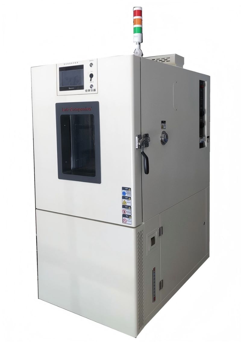
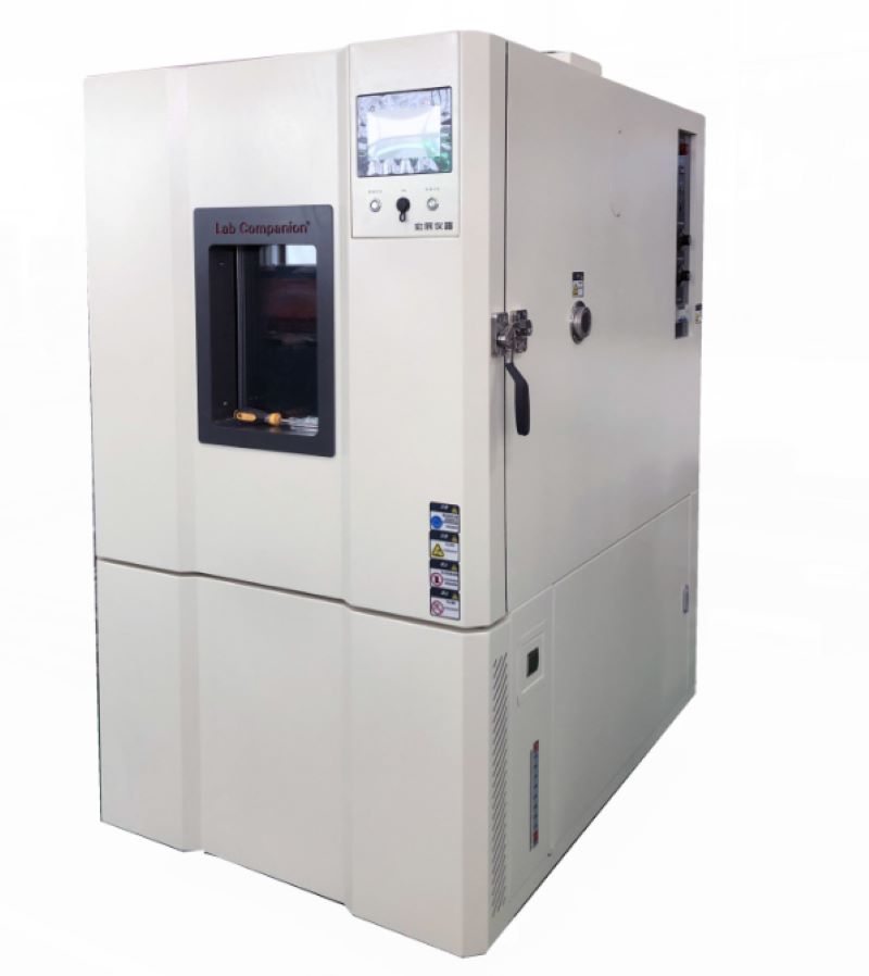
Setting and Maintenance of Constant Temperature and Humidity Test Chamber
Constant temperature and humidity test chamber is a relatively precise test equipment. In order to ensure the smooth completion of each test process, the power supply of the connected equipment must be stable at around 380V to ensure that the compressor will not be damaged. In addition, you must ensure the personal safety of the personnel who receive the power, so please understand the specific operation methods before wiring.
Constant temperature and humidity test chamber adjust or replace the connected power supply. After checking that the voltage of the power supply to be connected is correct, connect the neutral terminal to the neutral terminal in the distribution chamber. Ensure that the neutral line is connected, otherwise it may cause the equipment of the constant temperature and humidity test chamber to fail to work normally or burn electrical components.
After confirming that the neutral wire is connected, connect the 3 ∮ wire to the three terminals under the main switch of the distribution chamber in the constant temperature and humidity test chamber, and tighten the screws. We need to connect the ground wire, which is connected in the same way as other power cables, and directly to the ground terminal of the distribution chamber. In the process of connecting each power cord, everyone must ensure that the different colors of the power cord can be correctly identified to avoid connection errors and normal testing.
Maintenance of constant temperature and humidity test chamber:
1, Clean the water circulation system: clean the water filter, replace the filter, check the operation of the pump, including the operation of the water flow switch, adjust the water circulation flow and test operation.
2, Check all electrical wiring and electrical components to ensure reliable operation and good contact.
3, Replace the fresh air filter.
4, Refrigeration system cleaning: replace the refrigeration oil, clean the oil filter.
5, Check the vulnerable parts of the refrigeration system: check the sealing condition of the compressor and connecting parts, and replace all filters.
6, Refrigeration system leakage inspection: check all the connecting parts of the refrigeration system and the connecting parts of the valve plate are leaked and tightened.
7, According to the working conditions to supplement refrigerant: check whether the need to supplement the system refrigerant to ensure effective cooling capacity.
8, Comprehensive system operation: check whether the operating components are in good condition.
The Measuring Principle of Hygrometer in High and Low Temperature Test Chamber
Temperature and humidity is the percentage of the amount of water vapor (vapor pressure) contained in a gas (usually air) and the amount of saturated water vapor (saturated vapor pressure) in the same case as the air, expressed in RH%. Humidity long ago had a close relationship with life, but it was difficult to quantify it. The expression of humidity is humidity, relative humidity, dew point, ratio of moisture to dry gas (weight or volume), and so on.
Humidity measurement method hygrograph humidity measurement from the principle of the division of twenty or thirty. But humidity measurement is always one of the difficult problems in the world measurement field. A seemingly simple quantity value, in depth, involves quite complex physico-chemical theoretical analysis and calculation, beginners may ignore many factors that must be paid attention to in humidity measurement, thus affecting the reasonable use of sensors.
Common humidity measurement methods are: dew point method, wet and dry bulb method and electronic sensor method, dynamic method (double pressure method, double temperature method, shunt method), static method (saturated salt method, sulfuric acid method)
1, Dew point method hygrograph: is to measure the temperature when the wet air reaches saturation, is a direct result of thermodynamics, high accuracy, wide measurement range. Precision dew point instrument for measurement can reach ±0.2°C or even higher accuracy. However, the cold mirror dew-point meter with modern optoelectric principle is expensive and often used with standard humidity generators.
2, Wet and dry bulb hygrometer: this is a wet measurement method invented in the 18th century. It has a long history and is widely used. Wet and dry bulb method is an indirect method, which converts the humidity value from the wet and dry bulb equation, and this equation is conditional: that is, the wind speed near the wet bulb must reach more than 2.5m/s. The common wet and dry bulb thermometer simplifies this condition, so its accuracy is only 5~7%RH, and the wet and dry bulb does not belong to the static method, do not simply think that improving the measurement accuracy of the two thermometers is equal to improving the measurement accuracy of the hygrometer.
3, Electronic humidity sensor method hygrometer: electronic humidity sensor products and humidity measurement belong to the industry that rose in the 1990s in recent years, at home and abroad in the field of humidity sensor research and development has made great progress. Humidity sensors are developing rapidly from simple humidity sensors to integrated, intelligent, multi-parameter detection, creating favorable conditions for the development of a new generation of humidity measurement and control systems, and also raising humidity measurement technology to a new level.
4, Double pressure method, double temperature hygrometer: is based on the thermodynamic P, V, T balance principle, the balance time is longer, shunt method is based on the precise mixing of moisture and dry air. Due to the use of modern measurement and control means, these devices can be quite precise, but because of the complex equipment, expensive, time-consuming operation, mainly used as standard measurement, its measurement accuracy can reach ±2%RH or more.
5, Static method of saturated salt hygrometer: is a common method in humidity measurement, simple and easy. However, the saturated salt method has strict requirements for the balance of liquid and gas two phases, and high requirements for the stability of ambient temperature. It requires a long time to balance, and low humidity points require even longer. Especially when the humidity difference between the indoor and the bottle is large, it needs to be balanced for 6 to 8 hours each time it is opened.
Composition of Electrical Components of High and Low Temperature Test Chamber
The main parts of high and low temperature test chamber are refrigeration units, condensers, evaporators, and controllers. The main parts play a key role, so everyone pays special attention to its main parts raw materials. However, most of them ignore its auxiliary parts at this time, or feel that the role of auxiliary parts is not worth noting. Few people want to count the specific parts, so it is not clear what specific electronic components are fully used in the constant temperature and humidity test chamber.
1, Refrigeration unit:
Used to control the operation of refrigeration unit, to carry out refrigeration cycle, and there are single-phase and three-phase.
2, Fan motor:
Used to control the fan circulation steam body, heat exchanger heat conduction, and there are indoor and outdoor.
3, Electric heater equipment:
Used for heating indoor air quality quality, tubular, flocculent points.
4, Timer:
Used for automatic control system timing boot.
5, DC contactor:
Used for refrigeration unit motor breaking and connection.
6, Leakage protector power switch:
It can not only connect or disconnect the main circuit like other switches, with the effect of leakage current detection and discrimination, when the main control circuit caused by power outage or cable sheath damage, leakage protection switch power supply main switch can be connected or disconnected switch components according to the identification results. It can be combined with isolation switch and heat relay to form a full-function low-voltage switching electronic device.
7, Overtemperature protection equipment:
Its role can not be ignored, when the controller temperature is not sensitive, the implementation of the E double maintenance of the box overtemperature, when the alarm is caused, the maintenance standby, the alarm will be different with the test temperature, relative change, you can further have the role of overtemperature maintenance. The basic concept is that when the total current flow of the broken wire exceeds the limit value, the temperature of the broken wire rises and the broken wire is broken. When the heat value caused by the broken wire does not exceed its short circuit capacity, the balance between the heat value and the released heat value is guaranteed, the temperature of the broken wire cannot reach the melting temperature, it is not easy to break.
Like this kind of small electronic components, in the high and low temperature test chamber looks innocuous, but for the structure of a test chamber is also very useful, without these components, a test chamber is not used, in short, the details determine the success of failure, fine without size, in the grasp of the test chamber at the same time, more should be from its key links to grasp.
Sealing Problems and Solutions of High and Low Temperature Test Chamber
High and low temperature test chamber is based on the natural environment such as high temperature, ultra-low temperature, high and low temperature and low temperature drying in the room during the construction of work, and then carries out high and low temperature test and temperature and humidity aging resistance experiment on the commodity, mainly used for industrial products, such as: electronic and electrical, instrumentation equipment, cars and motorcycles, universities and other manufacturing industries.
Because of high temperature testing, ultra-low temperature testing, high and low temperature test cycle system testing, high and low temperature test and other experimental standards, high and low temperature test chamber in the high temperature standards, such as doing 150 ° C extremity of high temperature and 98% of the ambient humidity conditions, and the pressure difference between inside and outside the laboratory to expand substantially, at this moment, the sealing effect of the test chamber really matters. If the airtightness is not very good, it will cause more serious vapor leakage, affecting the precision and accuracy of the temperature.
What are the factors that cause the sealing problem of the high and low temperature test chamber?
First, the constant temperature and humidity test chamber usually has cable holes and ventilation exhaust holes, and the design scheme is very strict.
If the design scheme and production are not scientific, the gap will be too large, and the sealing of the environmental test chamber will not be good. This punching studio should also remember to plug the suitable specifications of the bottle stopper, rubber stopper, etc., to ensure that the sealing of this punching place is intact.
Second, the problem of sealing rubber strips of high and low temperature test chamber. We usually ignore this problem, feel that the sealing strip is added to the door hinge, and should be very sealable under the inhibition of the door hinge, because the aging of the silicone seal, the selection of hard flexibility is unscientific, and the sealing strip is fixed and not the same, often causing steam leakage. It is also simple to handle, often test its tightness, and find that the embrittlement of the sealing strip must be replaced as soon as possible.
Third, because the general volume of the high and low temperature test chamber is relatively large, the tail door specifications are expanded, and the net weight is very large, and the vertical orientation of the door hinge is offset after the long-term load, and the tail door is shifted and closed. Such problems are usually dealt with according to the modified high-load door hinges and the total number of door hinges.
From the above analysis, it can be seen that the sealing problem of the high and low temperature test chamber has some design problems and some maintenance problems. Therefore, we should strictly follow the equipment maintenance manual for regular maintenance in the use of equipment to ensure the normal operation of equipment and no deviation of technical parameters.
High and Low Temperature Test Chamber Requirements Specified in the Standard
The test chamber requirements formulated according to relevant standards should meet the following two points:
1. The temperature and humidity in the high and low temperature test chamber are monitored by the sensor installed in the working space. For the test of the heat dissipation test sample, the installation position of the sensor is formulated in the GB/T2421-1999 standard.
2, The temperature and relative humidity of the working space are required to be constant within the nominal value and its specified tolerance range, and the influence of the test sample should also be considered during the test.
Heat dissipation test sample test:
The volume of the high and low temperature test chamber should be at least 5 times the total volume of the test sample, the distance between the test sample and the internal wall of the test chamber should be selected according to the provisions of GB/T2423.2-2001 Appendix A (standard appendix), the wind speed in the chamber should not exceed 1M/S, and the structure of the mounting frame or support frame of the test chamber sample should simulate the real conditions in use as much as possible. Or otherwise, the effect of the sample mounting rack on the exchange of heat and moisture between the test sample and the surrounding space should be reduced to a minimum, and the relevant specifications may also specify dedicated mounting racks.
Test severity level:
The severity grade of the test chamber consists of the test temperature, relative humidity and test time, and is specified by the relevant specifications. The combination of temperature and relative humidity can be selected from the following values:
a, 30℃±2℃ 93%±3%
b, 30℃±2℃ 85%±3%
c, 40℃±2℃ 93%±3%
d, 40℃±2℃ 85%±3%
During the test, the test chamber shall be at the temperature and humidity of the laboratory, and the test sample at the ambient temperature of the laboratory shall be placed in the normal position or other specified position in the laboratory in an unpacked, unenergized, "ready for use" state, under certain circumstances (e.g. The relevant specifications may allow the test sample to be directly sent into the test chamber under the treated test conditions, but the test sample must be prevented from producing condensation, the temperature in the test chamber should be adjusted to a predetermined severity level, the time should ensure that the test sample reaches temperature stability, the test time should be calculated from the specified conditions, if the relevant specifications require, the test sample can be energized or worked in the conditional test phase, and the relevant specifications should specify the working conditions and working time or cycle of the test sample during the test. At the end of the conditional test, the test sample should still be left in the test chamber and the chamber should be adjusted to the standard atmospheric conditions of the test. The relative humidity should be reduced first, and the time should not exceed 2 hours. The temperature change rate in the test chamber should not exceed 1℃/min on average within 5min, and the relative humidity during temperature regulation should not exceed 75%. After the conditional test, the test sample should enter the recovery procedure.
Principles That Operating Constant Temperature and Humidity Test Chamber Should Follow
Constant temperature and humidity test chamber, also known as constant temperature and humidity test machine, programmable temperature and humidity alternating test chamber, thermostat or constant temperature and humidity chamber, can be used to test various environments and test equipment material performance, this material has heat resistance, cold resistance, dry resistance and humidity resistance. However, when using the constant temperature and humidity test chamber, the correct operation helps to obtain scientific data for the experimenter, so what principles should be followed in the operation of the constant temperature and humidity test chamber?
First, in the environmental test, the operator must be familiar with the required test sample performance, test conditions, test procedures and test technology, familiar with the technical performance of the test equipment used, and understand the structure of the equipment, especially familiar with the control operation and performance. At the same time, read the operation manual of the test equipment carefully to avoid abnormal operation of the test equipment due to operation errors, which may cause damage to the test sample and incorrect test data.
Second, in order to ensure the normal operation of the test, appropriate testing equipment should be selected according to the different conditions of the test sample, and a reasonable proportion between the temperature and humidity of the test sample and the effective volume of the laboratory should be maintained. For tests of heated test samples, the volume should not be greater than one-tenth of the effective volume of the test chamber. The volume of the unheated test sample should not exceed one-fifth of the effective volume of the test chamber.
Third, for environmental tests that need to add media to the test, it should be correctly added according to the test requirements. For example, there are certain requirements for water in temperature and humidity test chambers and the resistance should be reduced. There is a more economical and convenient form of pure water on the market. Its resistance is equivalent to distilled water.
Fourth, wet bulb gauze (wet bulb paper) has certain requirements for use in a temperature and humidity test chamber, and no gauze can be replaced, because the relative humidity reading is the difference between the root distance and temperature and humidity, and strictly speaking, it is also related to the local atmospheric pressure and wind speed at the time. The indicator value of wet-bulb temperature is related to the amount of water absorbed by the gauze and the amount of surface evaporation. These are directly related to the quality of the gauze, so the weather stipulates that the wet ball gauze must be a special "wet ball gauze" woven from linen. Otherwise, it is difficult to ensure the correctness of the wet bulb thermometer value, that is, the correctness of the humidity. In addition, the position of the wet gauze is also clearly specified. Gauze length: 100mm, tightly wrap the sensor probe, probe 25-30mm away from the humidity cup, gauze immersed in the cup to ensure the accuracy of equipment control and humidity.
Fifth, the location of the test sample should be more than 10 cm away from the wall of the chamber, and multiple samples should be placed on the same plane as far as possible. Samples should be placed without blocking air outlets and return vents, and temperature and humidity sensors should be kept at a distance. Make sure the test temperature is correct.
Operating the constant temperature and humidity test chamber in accordance with the above principles, the correct operation of the test process will greatly improve the level of test data. As long as the above principles are adhered to, it should be said that the temperature and humidity tests can be successfully performed.
Introduction and Comparison of Thermocouple Temperature Sensing Lines
Instructions:
The background principle of thermocouple is "seebeck effect", also known as the thermoelectric effect, the phenomenon is that when two different metal endpoints are connected to form a closed loop, and if there is a temperature difference between the two endpoints, then there will be current generated between the loops, and the higher temperature contact in the loop is called "hot junction". This point is usually placed at the temperature measurement; The lower end of the temperature is called "cold junction", that is, the output end of the thermocouple, whose output signal is: DC voltage is converted into a digital signal through the A/D converter and converted into the actual temperature value through the softwares algorithm.
Various electric heating couples and their range of use(ASTM E 230 T/C):
type E
type J
type K
-100℃ to 1000℃±0.5℃
0℃ to 760℃±0.1℃
0℃ to 1370℃±0.7℃
Brown (skin color)+ purple - red
Brown (skin color)+ white - red
Brown (skin color)+ yellow - red
JIS,ANSI(ASTM) thermoelectric coupling appearance identification:
Thermoelectric coupling
JIS
ANSI(ASTM)
Rind
Positive end
Negative end
Rind
Positive end
Negative end
B type
Grayish
Red
white
Grayish
Grayish
Red
R,S type
Brown
Red
white
Green
Brown
Red
K,W,V type
Green
Red
white
Yellow
Yellow
Red
E type
Purple
Red
white
Purple
Purple
Red
J type
Yellow
Red
white
Brown
white
Red
T type
Tawny
Red
white
Green
Green
Red
Note:
1.ASTM, ANSI: American standard
2.JIS: Japanese standard
High and Low Temperature Test Standard for PC Plastic Material
First, high temperature test
After being placed at 80±2°C for 4 hours and at normal temperature for 2 hours, the dimensions, insulation resistance, voltage resistance, key function, and loop resistance should meet normal requirements, and the appearance should not be deformed, warped, or degumming. Key bumps collapsing at high temperatures and reduced pressing force are not evaluated.
Second, low temperature test
After being placed at -30±2℃ for 4 hours and at normal temperature for 2 hours, the dimensions, insulation resistance, voltage resistance, key function, and loop resistance should meet normal requirements, and the appearance should not be deformed, warped, or degumming.
Third, temperature cycling test
After being placed in 70±2℃ for 30 minutes, remove at room temperature for 5 minutes; then after being placed in -20±2℃ for 30 minutes, remove at room temperature for 5 minutes. After such 5 cycles, the dimensions, insulation resistance, voltage resistance, key function, and loop resistance should meet normal requirements, and the appearance should not be deformed, warped, or degumming. Key bumps collapsing at high temperatures and reduced pressing force are not evaluated.
Fourth, heat resistance
After being placed in an environment with a temperature of 40±2℃ and a relative humidity of 93±2%RH for 48 hours, the dimensions, insulation resistance, voltage resistance, key function, and loop resistance should meet normal requirements, and the appearance should not be deformed, warped, or degumming. Key bumps collapsing at high temperatures and reduced pressing force are not evaluated.
Composition and Application of Temperature and Humidity Regulating Chamber
Temperature and humidity regulating chamber is a device that controls the ambient temperature and humidity. It can provide a stable temperature and humidity environment to meet the requirements of a specific product or experiment. Temperature and humidity regulating chamber is usually composed of a control system, a heating system, a cooling system, a humidity control system and a circulation system.
In terms of working principle, temperature and humidity regulating chamber realizes temperature control through the control system to control the operation of the heating system and the refrigeration system. When the temperature is too low, the heating system starts and provides heat to raise the temperature; When the temperature is too high, the refrigeration system starts and absorbs heat to reduce the temperature. In this way, the temperature regulator can maintain a stable operating temperature.
The humidity control system of temperature and humidity regulating chamber is used to maintain a proper humidity level. When the humidity is too low, the humidity control system releases water vapor to increase the humidity; When the humidity is too high, the humidity control system absorbs the excess humidity to reduce the humidity. With precise humidity control, temperature regulators ensure that the ambient humidity is within the ideal range.
Temperature and humidity regulating chamber is widely used in practical applications. Taking the pharmaceutical industry as an example, some drugs have high requirements for temperature and humidity during processing and storage. If the ambient temperature and humidity are not effectively controlled, the quality and stability of these drugs will be affected. The temperature regulator can provide a stable working environment to ensure the quality and efficiency of the drug.
In the food industry, Temperature and humidity regulating chamber also plays an important role. For example, in the chocolate manufacturing process, the control of temperature and humidity directly affects the texture and taste of chocolate. The temperature regulator accurately controls temperature and humidity, ensuring that the chocolate production process meets standards and produces quality products.
Temperature and humidity regulating chamber is also widely used in electronic, chemical and other industries. In the electronics industry, temperature and humidity control is very important for the production and storage of electronic components. In the chemical industry, some chemical reactions have high requirements for temperature and humidity, which can provide a stable and safe working environment.
New Energy Environment Test Solution
The problem of new energy reliability is still difficult, and the integrated detection system of electrical stress and environmental stress will provide the best means for research and development and manufacturing.
Industry
Test object
Use
Technology
Solution
New Energy
Battery (secondary battery)
Inspect
Charge and discharge test
High and low temperature (&humidity) test chamber
Rapid temperature (&humidity)change test chamber
Evaluate
Characteristic test
Rapid temperature (&humidity)change test chamber
Fuel cell
/
Temperature resistance
Small ultra-low temperature test chamber
High and low temperature (&humidity) test chamber
Rapid temperature (&humidity)change test chamber
Environmental Test Solutions for Electronic Products
The statistical analysis shows that the failure of electronic components accounts for 50% of the failure of electronic complete machine, and the reliability detection technology still faces many challenges.
Industry
Test object
Use
Technology
Solution
Electronic products
Semiconductor
Evaluate
Evaluation of adhesion between equipment and substrate
Rapid temperature (&humidity)change test chamber
Printed circuit board
Manufacture
Hardening and drying of insulating coatings
High temperature test chamber
Accelerated thermal cycling test
Rapid temperature (&humidity)change test chamber
Low temperature placement test
Rapid temperature (&humidity)change test chamber
LED
Evaluate
High temperature test
High temperature test chamber
Temperature cycling test
High and low temperature (&humidity) test chamber
Temperature cycling test
Rapid temperature (&humidity)change test chamber
Magnetic material
Manufacture
Drying
High temperature test chamber
/
High and low temperature (&humidity) test chamber
Battery
Evaluate
Characteristic test
Rapid temperature (&humidity)change test chamber
Environmental Test Solutions For Mechanical And Electrical Products
The statistical analysis shows that the failure of electronic components accounts for 50% of the failure of electronic complete machine, and the reliability detection technology still faces many challenges.
Industry
Test object
Use
Technology
Solution
Electromechanical
System component
Evaluate
Thermal cycling test
High and low temperature (&humidity) test chamber
Thermal cycling test
Rapid temperature (&humidity)change test chamber
Electric gas
Evaluate
Thermal cycling test
High and low temperature (&humidity) test chamber
Thermal cycling test
Rapid temperature (&humidity)change test chamber
Railway traffic
Evaluate
Thermal cycling test
High and low temperature (&humidity) test chamber
Thermal cycling test
Rapid temperature (&humidity)change test chamber
/
High and low temperature (&humidity) test chamber
/
Small ultra-low temperature test chamber


 Get A Quote


 IPv6 network supported