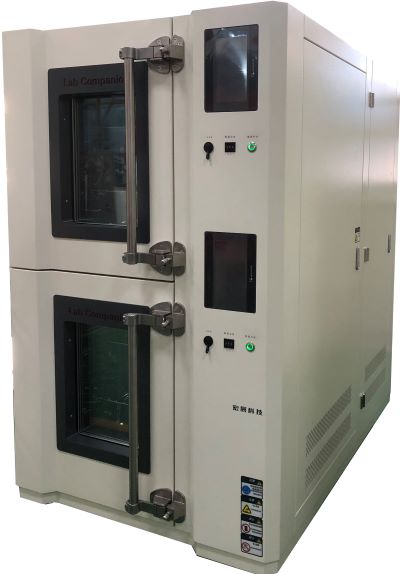
Sealing Problems and Solutions of High and Low Temperature Test Chamber
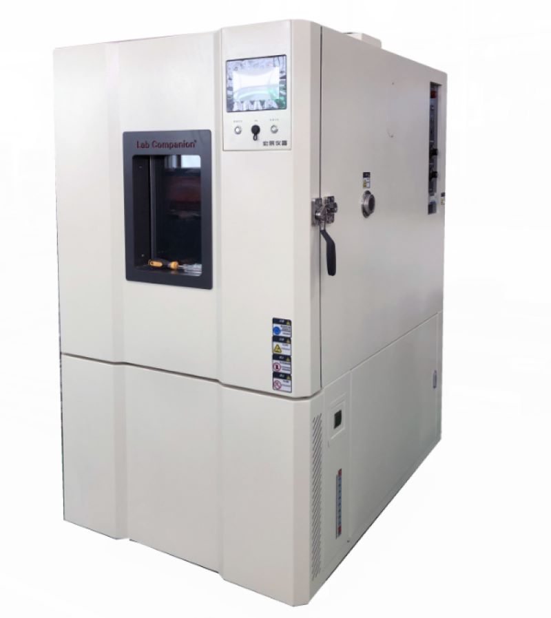
High and low temperature test chamber is based on the natural environment such as high temperature, ultra-low temperature, high and low temperature and low temperature drying in the room during the construction of work, and then carries out high and low temperature test and temperature and humidity aging resistance experiment on the commodity, mainly used for industrial products, such as: electronic and electrical, instrumentation equipment, cars and motorcycles, universities and other manufacturing industries.
Because of high temperature testing, ultra-low temperature testing, high and low temperature test cycle system testing, high and low temperature test and other experimental standards, high and low temperature test chamber in the high temperature standards, such as doing 150 ° C extremity of high temperature and 98% of the ambient humidity conditions, and the pressure difference between inside and outside the laboratory to expand substantially, at this moment, the sealing effect of the test chamber really matters. If the airtightness is not very good, it will cause more serious vapor leakage, affecting the precision and accuracy of the temperature.
What are the factors that cause the sealing problem of the high and low temperature test chamber?
First, the constant temperature and humidity test chamber usually has cable holes and ventilation exhaust holes, and the design scheme is very strict.
If the design scheme and production are not scientific, the gap will be too large, and the sealing of the environmental test chamber will not be good. This punching studio should also remember to plug the suitable specifications of the bottle stopper, rubber stopper, etc., to ensure that the sealing of this punching place is intact.
Second, the problem of sealing rubber strips of high and low temperature test chamber. We usually ignore this problem, feel that the sealing strip is added to the door hinge, and should be very sealable under the inhibition of the door hinge, because the aging of the silicone seal, the selection of hard flexibility is unscientific, and the sealing strip is fixed and not the same, often causing steam leakage. It is also simple to handle, often test its tightness, and find that the embrittlement of the sealing strip must be replaced as soon as possible.
Third, because the general volume of the high and low temperature test chamber is relatively large, the tail door specifications are expanded, and the net weight is very large, and the vertical orientation of the door hinge is offset after the long-term load, and the tail door is shifted and closed. Such problems are usually dealt with according to the modified high-load door hinges and the total number of door hinges.
From the above analysis, it can be seen that the sealing problem of the high and low temperature test chamber has some design problems and some maintenance problems. Therefore, we should strictly follow the equipment maintenance manual for regular maintenance in the use of equipment to ensure the normal operation of equipment and no deviation of technical parameters.
Cooling Mode of Condenser in High and Low Temperature Test Chamber
High and low temperature test chamber is a common temperature test equipment in environmental test equipment, which is suitable for high temperature and low temperature reliability test of industrial products. The working principle of refrigeration in the high and low temperature test chamber is that the refrigerant flows out of the condenser under high pressure, passes through the throttling mechanism (capillary, thermal expansion valve, etc.), reduces its pressure, and then enters the evaporator. When the refrigeration medium enters the evaporator, it is a two-phase mixture (liquid and gas), which evaporates and absorbs heat under low temperature conditions in the evaporator. It then enters the condenser, where heat is released and condensed into a liquid. Xenon lamp aging test chamber uses xenon lamp with long arc as light source, which can provide corresponding environmental simulation and accelerated test for scientific research, product development and quality control. The vehicle environment simulation laboratory can simulate the test environment of engine cold start, vehicle high and low temperature, wind, frost, rain, snow, vehicle emission test, etc.
According to different refrigeration media, the cooling mode of the high and low temperature test chamber condenser can be divided into three types: air cooling, water cooling and liquid nitrogen refrigeration. Their medium is refrigerant, water and liquid nitrogen. Different media correspond to different evaporation temperatures, the same medium under different evaporation pressure, evaporation temperature is not the same.
The different cooling methods of the condenser in the high and low temperature test chamber make the components of the refrigeration different. The air cooling method consists of compressor, various refrigeration accessories, condenser, oil separator and so on. The water cooling method consists of: chiller, cooling tower, freezing pump and auxiliary equipment. Liquid nitrogen is composed of: liquid nitrogen tank, pressure transmitter, pressure gauge, flow meter, level meter, ultra-low temperature solenoid valve and so on.
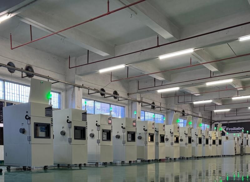
No matter what kind of cooling method is used in the high and low temperature test chamber condenser, high reliability and safety are the most basic requirements. Instrument test equipment of Lab Companion can provide a variety of condenser cooling methods according to customer needs.
In addition to the high and low temperature test chamber, instrument of Lab Companion also produces all kinds of temperature and humidity test chamber, constant temperature and humidity test equipment, aging chamber (ultraviolet, xenon lamp, ozone aging chamber), thermal shock test chamber, high temperature aging machine and other equipment, all the equipment is produced according to national standards and industry specifications.
Efficacy of Electronic Expansion Valve in High and Low Temperature Test Chamber
The electronic expansion valve of the high and low temperature test chamber adjusts the water supply rate of the air conditioning evaporator according to the preset program flow, which is called the electronic expansion valve because it belongs to the electronic adjustment mode. It integrates the development trend of refrigeration mechatronics, with the unparalleled characteristics of the expansion valve, and presents the standard for the intelligent system operation of the refrigeration system of the quotation of the high and low temperature test chamber. It is a kind of automatic control environmental protection and energy-saving components with great development prospects, and is the orientation of the development trend of the quotation of the high and low temperature test chamber in the future.
The main purpose of the electronic expansion valve and the hot air conditioning expansion valve is basically the same, and the structure is various, but in the characteristics, the two have great differences. From the perspective of control and maintenance, the electronic expansion valve is composed of three parts: control board, electric actuator and controller. Generally speaking, most of the electronic expansion valve only refers to the electric actuator, that is, the controllable drive equipment and the oil circuit board. In fact, only this part is unable to operate.
The key hardware configuration of the electronic expansion valve control board is designed by single chip microcomputer, such as the control board also needs to operate the DC frequency conversion of the refrigeration compressor and the centrifugal fan, and the method of multi-machine cascade is generally selected. The controller of the electronic expansion valve generally uses thermal resistance or thermal resistance. As a new type of hydraulic control system, electronic expansion valve has been early to improve the definition of throttle organization, which is the key step of the intelligent system of refrigeration system, is the key way and ensure that the refrigeration system is upgraded enough to truly maintain, is a representative of the mechanical and electrical engineering of refrigeration system, has been used in more and more industries. Because of the selection of electronic expansion valves, the awareness of a certain type of system submission to expansion valves existing in the whole process of the refrigeration unit design scheme has been enhanced, and the new pattern of air conditioning expansion valves for system improvement services has played a key role in the development trend of the refrigeration manufacturing industry.
The high and low temperature test chamber can complete the test process according to the pre-set curve, and can accurately control the temperature rate within the range of the heating rate capacity, and can control the heating and cooling rate according to the slope of the set curve.
Temperature control is a heating process, high and low temperature test chamber heating using independent heating, far infrared nickel-chromium alloy high-speed heating wire, P.I.D+S.R system co-channel coordinated temperature control, through microcomputer calculation of output power, to obtain high-precision, high-efficiency electricity benefits. In order to achieve rapid heating and high temperature, the method of increasing the number of heating wires and improving the temperature control performance of software is generally adopted. By using international brand compressors and circulating fans, the chamber has uniform temperature distribution, high efficiency for environment-friendly refrigerant, low energy consumption and saved energy. The use of energy regulation technology in the design of refrigeration system can not only ensure the normal operation of the unit, but also effectively adjust the energy consumption and cooling capacity, so that the refrigeration system is in a good running state.
High and Low Temperature Test Chamber Requirements Specified in the Standard
The test chamber requirements formulated according to relevant standards should meet the following two points:
1. The temperature and humidity in the high and low temperature test chamber are monitored by the sensor installed in the working space. For the test of the heat dissipation test sample, the installation position of the sensor is formulated in the GB/T2421-1999 standard.
2, The temperature and relative humidity of the working space are required to be constant within the nominal value and its specified tolerance range, and the influence of the test sample should also be considered during the test.
Heat dissipation test sample test:
The volume of the high and low temperature test chamber should be at least 5 times the total volume of the test sample, the distance between the test sample and the internal wall of the test chamber should be selected according to the provisions of GB/T2423.2-2001 Appendix A (standard appendix), the wind speed in the chamber should not exceed 1M/S, and the structure of the mounting frame or support frame of the test chamber sample should simulate the real conditions in use as much as possible. Or otherwise, the effect of the sample mounting rack on the exchange of heat and moisture between the test sample and the surrounding space should be reduced to a minimum, and the relevant specifications may also specify dedicated mounting racks.
Test severity level:
The severity grade of the test chamber consists of the test temperature, relative humidity and test time, and is specified by the relevant specifications. The combination of temperature and relative humidity can be selected from the following values:
a, 30℃±2℃ 93%±3%
b, 30℃±2℃ 85%±3%
c, 40℃±2℃ 93%±3%
d, 40℃±2℃ 85%±3%
During the test, the test chamber shall be at the temperature and humidity of the laboratory, and the test sample at the ambient temperature of the laboratory shall be placed in the normal position or other specified position in the laboratory in an unpacked, unenergized, "ready for use" state, under certain circumstances (e.g. The relevant specifications may allow the test sample to be directly sent into the test chamber under the treated test conditions, but the test sample must be prevented from producing condensation, the temperature in the test chamber should be adjusted to a predetermined severity level, the time should ensure that the test sample reaches temperature stability, the test time should be calculated from the specified conditions, if the relevant specifications require, the test sample can be energized or worked in the conditional test phase, and the relevant specifications should specify the working conditions and working time or cycle of the test sample during the test. At the end of the conditional test, the test sample should still be left in the test chamber and the chamber should be adjusted to the standard atmospheric conditions of the test. The relative humidity should be reduced first, and the time should not exceed 2 hours. The temperature change rate in the test chamber should not exceed 1℃/min on average within 5min, and the relative humidity during temperature regulation should not exceed 75%. After the conditional test, the test sample should enter the recovery procedure.
Principles That Operating Constant Temperature and Humidity Test Chamber Should Follow
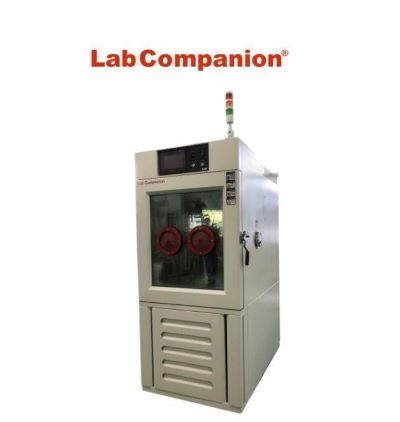
Constant temperature and humidity test chamber, also known as constant temperature and humidity test machine, programmable temperature and humidity alternating test chamber, thermostat or constant temperature and humidity chamber, can be used to test various environments and test equipment material performance, this material has heat resistance, cold resistance, dry resistance and humidity resistance. However, when using the constant temperature and humidity test chamber, the correct operation helps to obtain scientific data for the experimenter, so what principles should be followed in the operation of the constant temperature and humidity test chamber?
First, in the environmental test, the operator must be familiar with the required test sample performance, test conditions, test procedures and test technology, familiar with the technical performance of the test equipment used, and understand the structure of the equipment, especially familiar with the control operation and performance. At the same time, read the operation manual of the test equipment carefully to avoid abnormal operation of the test equipment due to operation errors, which may cause damage to the test sample and incorrect test data.
Second, in order to ensure the normal operation of the test, appropriate testing equipment should be selected according to the different conditions of the test sample, and a reasonable proportion between the temperature and humidity of the test sample and the effective volume of the laboratory should be maintained. For tests of heated test samples, the volume should not be greater than one-tenth of the effective volume of the test chamber. The volume of the unheated test sample should not exceed one-fifth of the effective volume of the test chamber.
Third, for environmental tests that need to add media to the test, it should be correctly added according to the test requirements. For example, there are certain requirements for water in temperature and humidity test chambers and the resistance should be reduced. There is a more economical and convenient form of pure water on the market. Its resistance is equivalent to distilled water.
Fourth, wet bulb gauze (wet bulb paper) has certain requirements for use in a temperature and humidity test chamber, and no gauze can be replaced, because the relative humidity reading is the difference between the root distance and temperature and humidity, and strictly speaking, it is also related to the local atmospheric pressure and wind speed at the time. The indicator value of wet-bulb temperature is related to the amount of water absorbed by the gauze and the amount of surface evaporation. These are directly related to the quality of the gauze, so the weather stipulates that the wet ball gauze must be a special "wet ball gauze" woven from linen. Otherwise, it is difficult to ensure the correctness of the wet bulb thermometer value, that is, the correctness of the humidity. In addition, the position of the wet gauze is also clearly specified. Gauze length: 100mm, tightly wrap the sensor probe, probe 25-30mm away from the humidity cup, gauze immersed in the cup to ensure the accuracy of equipment control and humidity.
Fifth, the location of the test sample should be more than 10 cm away from the wall of the chamber, and multiple samples should be placed on the same plane as far as possible. Samples should be placed without blocking air outlets and return vents, and temperature and humidity sensors should be kept at a distance. Make sure the test temperature is correct.
Operating the constant temperature and humidity test chamber in accordance with the above principles, the correct operation of the test process will greatly improve the level of test data. As long as the above principles are adhered to, it should be said that the temperature and humidity tests can be successfully performed.
Technical Means of Precise Temperature Control in High and Low Temperature Test Chamber
The high and low temperature test chamber is used to test the adaptability of materials or products in high and low temperature environments, and its accurate temperature control is achieved in the following ways:
1, Temperature control system
High and low temperature test chamber usually adopts temperature control system to achieve accurate temperature control. The system consists of temperature sensors, controllers and heaters. The temperature sensor is placed inside the test chamber to monitor the temperature change in real time, and the controller automatically controls the output power of the heater according to the signal of the sensor to achieve the purpose of accurate temperature control.
2, Temperature fluctuation control
Temperature fluctuation is an important index of accurate temperature control in high and low temperature test chamber. In order to ensure the stability of the temperature inside the test chamber, the controller will reduce the temperature fluctuation by adjusting the output power of the heater. Under normal circumstances, the accuracy of temperature fluctuations is required to be within 0.2°C.
3, Sealing control
The tightness of the high and low temperature test chamber is one of the important factors to ensure accurate temperature control. The tightness of the test chamber needs to be ensured by strict airtight testing to ensure that the heat inside the test chamber does not leak to the outside, or the heat from the outside does not enter the inside.
4, Time control
The time control of high and low temperature test chamber is also an important means to ensure accurate temperature control. The controller can set the test time according to the test needs, and automatically stop the test after the test time arrives to ensure the safety of the test sample.
In summary, the accurate temperature control of the high and low temperature test chamber is achieved through the joint action of many factors such as temperature control system, temperature fluctuation control, sealing control and time control.
Technical Characteristics of Refrigeration and Temperature Control System of High and Low Temperature Test Chamber
High and low temperature test chamber is a kind of test equipment widely used in various industries, which is widely used to simulate various environmental conditions and test the durability, reliability and corrosion resistance of products. The technical characteristics of the high and low temperature test chamber are mainly reflected in its refrigeration system and temperature control system.
First of all, the refrigeration system of the high and low temperature test chamber has a high refrigeration capacity and refrigeration speed. During the temperature control process, a refrigeration system is needed to quickly reduce the temperature inside the test chamber. At present, the mainstream refrigeration system mainly has two kinds of compression refrigeration system and refrigerant loop circulation system. Among them, the compression refrigeration system has a high refrigeration capacity and refrigeration speed, which can quickly reduce the temperature inside the test chamber to the set temperature, but also to ensure the stability of the temperature.
Secondly, the temperature control system of the high and low temperature test chamber has high accuracy and stability. The temperature control system is the core part of the whole test chamber, which realizes the accurate control and stability maintenance of the internal temperature of the test chamber through the adjustment and control of the refrigeration system and the heating system. The current mainstream temperature control system mainly includes PID control system and intelligent control system. Among them, the PID control system has the characteristics of high precision and high stability, which can realize the accurate control of the temperature inside the test chamber, and is suitable for the test environment with high requirements for temperature control accuracy. The intelligent control system has the characteristics of more intelligent, and can realize the automatic control and adjustment of the internal temperature of the test chamber through self-learning algorithm and big data analysis technology, which is suitable for the occasions with relatively broad test environment requirements.
In summary, the technical characteristics of the high and low temperature test chamber are mainly reflected in its refrigeration system and temperature control system. The compression refrigeration system and PID control system have the characteristics of high cooling capacity, high cooling speed, high temperature control accuracy and high stability, which are suitable for the test environment requiring high temperature control accuracy and stability. In the future, with the development of artificial intelligence and Internet of Things technology, the control system of high and low temperature test chamber will continue to develop and improve in the direction of intelligence, automation and remote control, so as to better meet market demand.
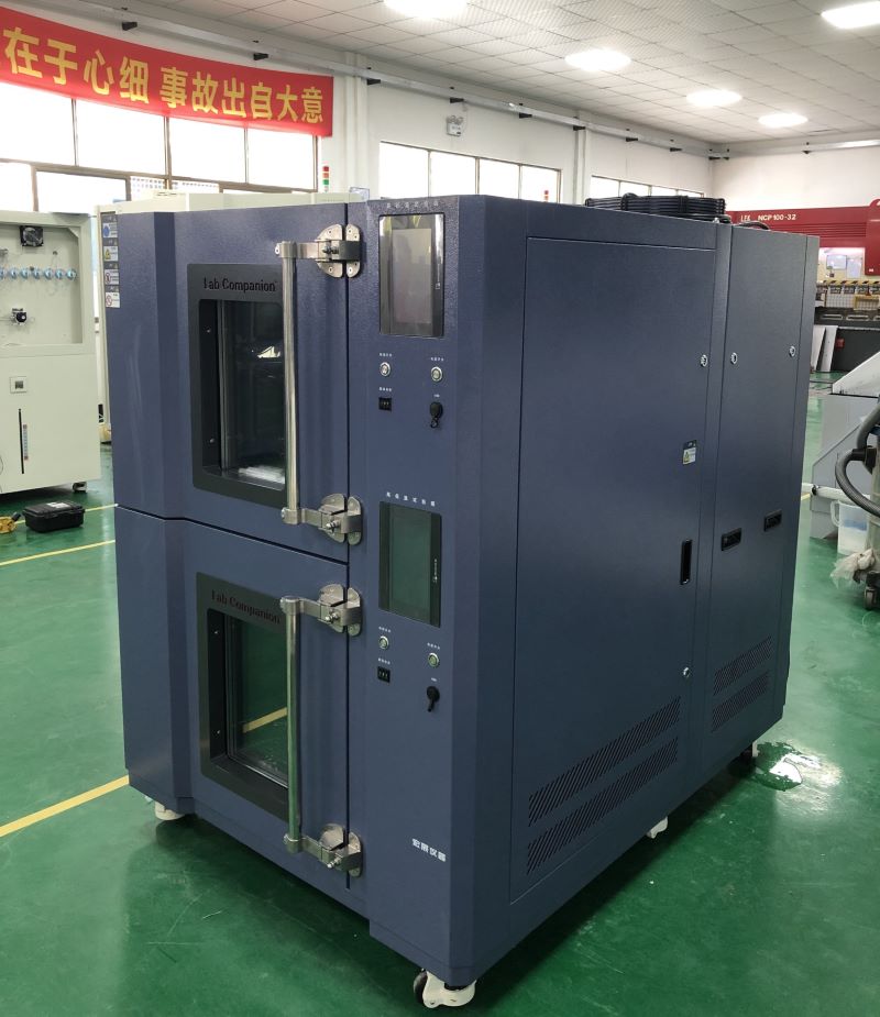
How to Change the Refrigerant Oil of Thermal Shock Test Chamber?
Thermal shock test chamber is a necessary test equipment for metal, plastic, rubber, electronics and other material industries, used to test material structure or composite materials, in an instant under the continuous environment of extremely high temperature and extremely low temperature to endure the degree of chemical changes or physical damage caused by thermal expansion and contraction of the sample in the shortest time. Thermal shock test chamberr meets the test method: GB/T2423.1.2, GB/T10592-2008, GJB150.3 thermal shock test.
In thermal shock test chamber, if the compressor is semi-closed piston compressor in operation for 500 hours, it is necessary to observe the oil temperature and oil pressure changes of the frozen oil, and if the frozen oil is discolored, it must be replaced. After the initial operation of the compressor unit for 2000 hours, the cumulative operation of three years or the operation time of more than 10,000 to 12,000 hours should be maintained within a time limit and the chilled oil should be replaced.
The refrigerated oil replacement of the semi-closed piston compressor in thermal shock test chamber can be performed according to the following steps:
1, Close high pressure exhaust and low pressure suction stop valve of thermal shock test chamber, and then screw down the oil plug, the oil plug is generally in the bottom of the crankcase, and then put the frozen oil clean and clean the filter.
2, Use the low-pressure impact gas valve needle to blow nitrogen into the oil port and then use the pressure to discharge the residual oil in the body, install a clean filter and tighten the oil plug.
3. Connect the low pressure tube filled with fluorine gauge to the low pressure process valve needle with a vacuum pump to pump the crankcase into negative pressure, and then remove the other fluorine tube separately, put one end into the chilled oil, and put the other end on the valve needle of the low pressure suction of the oil pump. The chilled oil is sucked into the crankcase due to the negative pressure, and add it to the position slightly higher than the lower limit of the oil mirror line.
4. After injection, tighten the process column or remove the fluorine filling tube, and then connect the fluorine pressure gauge to vacuum the compressor.
5. After vacuuming, it is necessary to open the high and low pressure stop valve of the compressor to check whether the refrigerant has leaked.
6, Open thermal shock test chamber unit to check the lubrication of the compressor and the oil level of the oil mirror, the oil level can not be less than a quarter of the mirror.
The above is how to replace the refrigerant oil of the semi-closed piston compressor in thermal shock test chamber. Because the refrigerant oil has hygroscope, the replacement process needs to reduce the air entering the system and the oil storage container. If the cold aging oil is injected too much, there is the risk of liquid shock.
What are the Types of PCB Environmental Tests?
High acceleration test:
Accelerated tests include high accelerated life test (HALT) and High accelerated Stress screening (HASS). These tests assess the reliability of products in controlled environments, including high temperature, high humidity, and vibration/shock tests when the equipment is powered on. The goal is to simulate the conditions that could lead to the imminent failure of a new product. During testing, the product is monitored in a simulated environment. Environmental testing of electronic products usually involves testing in a small environmental chamber.
Humidity and corrosion:
Many PCBS will be deployed in wet environments, so a common test for PCB reliability is a water absorption test. In this type of test, the PCB is weighed before and after being placed in a humidity controlled environmental chamber. Any water adsorbent on the board will increase the weight of the board, and any significant change in weight will result in disqualification.
When performing these tests during operation, exposed conductors should not be corroded in a humid environment. Copper oxidizes easily when it reaches a certain potential, which is why exposed copper is often plated with an antioxidant alloy. Some examples include ENIG, ENIPIG, HASL, nickel gold, and nickel.
Thermal shock and circulation:
Heat testing is usually performed separately from humidity testing. These tests include repeatedly changing the board temperature and checking how thermal expansion/contraction affects reliability. In thermal shock testing, the circuit board uses a two-chamber system to quickly move between two temperature extremes. The low temperature is usually below the freezing point, and the high temperature is usually higher than the glass transition temperature of the substrate (above ~130 ° C). The thermal cycle is carried out using a single chamber, with the temperature changing from one extreme to the other at a rate of 10°C per minute.
In both tests, the board expands or contracts as the board temperature changes. During the expansion process, conductors and solder joints are subjected to high stress, which speeds up the service life of the product and enables the identification of mechanical failure points.
Introduction and Comparison of Thermocouple Temperature Sensing Lines
Instructions:
The background principle of thermocouple is "seebeck effect", also known as the thermoelectric effect, the phenomenon is that when two different metal endpoints are connected to form a closed loop, and if there is a temperature difference between the two endpoints, then there will be current generated between the loops, and the higher temperature contact in the loop is called "hot junction". This point is usually placed at the temperature measurement; The lower end of the temperature is called "cold junction", that is, the output end of the thermocouple, whose output signal is: DC voltage is converted into a digital signal through the A/D converter and converted into the actual temperature value through the softwares algorithm.
Various electric heating couples and their range of use(ASTM E 230 T/C):
type E
type J
type K
-100℃ to 1000℃±0.5℃
0℃ to 760℃±0.1℃
0℃ to 1370℃±0.7℃
Brown (skin color)+ purple - red
Brown (skin color)+ white - red
Brown (skin color)+ yellow - red
JIS,ANSI(ASTM) thermoelectric coupling appearance identification:
Thermoelectric coupling
JIS
ANSI(ASTM)
Rind
Positive end
Negative end
Rind
Positive end
Negative end
B type
Grayish
Red
white
Grayish
Grayish
Red
R,S type
Brown
Red
white
Green
Brown
Red
K,W,V type
Green
Red
white
Yellow
Yellow
Red
E type
Purple
Red
white
Purple
Purple
Red
J type
Yellow
Red
white
Brown
white
Red
T type
Tawny
Red
white
Green
Green
Red
Note:
1.ASTM, ANSI: American standard
2.JIS: Japanese standard
High and Low Temperature Test Standard for PC Plastic Material
First, high temperature test
After being placed at 80±2°C for 4 hours and at normal temperature for 2 hours, the dimensions, insulation resistance, voltage resistance, key function, and loop resistance should meet normal requirements, and the appearance should not be deformed, warped, or degumming. Key bumps collapsing at high temperatures and reduced pressing force are not evaluated.
Second, low temperature test
After being placed at -30±2℃ for 4 hours and at normal temperature for 2 hours, the dimensions, insulation resistance, voltage resistance, key function, and loop resistance should meet normal requirements, and the appearance should not be deformed, warped, or degumming.
Third, temperature cycling test
After being placed in 70±2℃ for 30 minutes, remove at room temperature for 5 minutes; then after being placed in -20±2℃ for 30 minutes, remove at room temperature for 5 minutes. After such 5 cycles, the dimensions, insulation resistance, voltage resistance, key function, and loop resistance should meet normal requirements, and the appearance should not be deformed, warped, or degumming. Key bumps collapsing at high temperatures and reduced pressing force are not evaluated.
Fourth, heat resistance
After being placed in an environment with a temperature of 40±2℃ and a relative humidity of 93±2%RH for 48 hours, the dimensions, insulation resistance, voltage resistance, key function, and loop resistance should meet normal requirements, and the appearance should not be deformed, warped, or degumming. Key bumps collapsing at high temperatures and reduced pressing force are not evaluated.
Test Method and Standard for High and Low Temperature Environment of Industrial Tablet Computer
In many industrial control scenarios, high environmental adaptability of industrial control tablets, industrial control machines, and touch screens, especially the adaptability of temperature, is extremely needed. This article introduces test method and standard for high and low temperature environment of industrial tablet computers, industrial control machines, etc.
1. High temperature operation test
(1) Test the basic functions of the whole machine to check the appearance of the normal structure first. According to MIL-STD-810G method 501.5 high temperature process, when the whole machine is in working state, put it into the test chamber at the normal position, set the temperature at 60℃, connect the adapter to run the local 1080P video for 24 hours, check once every 12 hours hours, and set the heating and cooling time for 2 hours.
(2) Judging criteria: During the high temperature working period, there should be no system crash, restart, blue screen and other unstable system operation; Video image, touch, sound, key function check; Check the basic functions of the machine after the test, functional failure should not appear; the display should not appear watermarks, white dots, white spots, etc..
2. Low temperature operation test
(1) Test the basic functions of the whole machine to check the appearance of the normal structure first. According to MIL-STD-810G method 501.5 high temperature process, when the whole machine is in working state, put it into the test chamber at the normal position, set the temperature at -20℃, connect the adapter to run the local 1080P video for 24 hours, check once every 12 hours hours, and set the heating and cooling time for 2 hours.
(2) Judging criteria: During the high temperature working period, there should be no system crash, restart, blue screen and other unstable system operation; Video image, touch, sound, key function check; Check the basic functions of the machine after the test, functional failure should not appear; the display should not appear watermarks, white dots, white spots, etc…
3. high temperature storage test
(1) Test the basic functions of the whole machine first. Set the temperature at 70°C±2°C for 48 hours in shutdown state, heating and cooling time for 2 hours, normal temperature recovery for 1 hour and then check the power and basic functions.
(2) Judging criteria: room temperature environment, research and maintenance engineers test the basic function of the machine without functional problems; Check the appearance and structure of the product.
4. low temperature storage test
(1) Test the basic functions of the whole machine first. Set the temperature at -30°C±2°C for 24 hours in shutdown state, heating and cooling time for 2 hours, normal temperature recovery for 2 hour and then check the power and basic functions.
(2) Judging criteria: room temperature environment, research and maintenance engineers test the basic function of the machine without functional problems; Check the appearance and structure of the product.


 Get A Quote


 IPv6 network supported