Factors causing uneven temperature inside the high and low temperature humid heat test chamber
The high and low temperature damp heat test chamber is the main equipment in temperature and humidity environment testing, mainly used for conducting high and low temperature and humidity tests to evaluate the temperature and humidity resistance of products, so as to ensure that our products can work and operate normally under any environmental conditions. However, if the temperature uniformity exceeds the allowable deviation range during environmental testing in the high and low temperature damp heat test chamber, the data obtained from the test is unreliable and cannot be used as the ultimate tolerance for high and low temperature testing of materials or products. So what are the reasons that can cause temperature uniformity to exceed the allowable deviation range?
1. The differences in the test objects in the high and low temperature humid heat test chamber: If enough test samples that affect the overall internal heat convection are placed in the high and low temperature test chamber, it will inevitably affect the uniformity of the internal temperature to a certain extent, that is, the temperature uniformity. For example, if LED lighting products are placed, the products themselves emit light and heat, becoming a thermal load, which has a significant impact on temperature uniformity.
2. The design issues make it difficult to achieve a uniform symmetrical structure in the internal structure and space of the high and low temperature wet heat test chamber, and an asymmetric structure will inevitably lead to deviations in the uniformity of internal temperature. This aspect is mainly reflected in sheet metal design and processing, such as the design of air ducts, the placement of heating pipes, and the size of fan power. All of these will affect the temperature uniformity inside the box.
3. Due to the different structures of the inner wall of the high and low temperature humid heat test chamber, the temperature of the inner wall of the test chamber will also be uneven, which will affect the heat convection inside the working chamber and cause deviation in the internal temperature uniformity.
4. Due to the different heat transfer coefficients on the front, back, left, right, top, and bottom surfaces of the box wall in the studio, some have threading holes, detection holes, testing holes, etc., which cause local heat dissipation and transfer, resulting in uneven temperature distribution of the box body and uneven radiative convective heat transfer on the box wall, affecting temperature uniformity.
5. The sealing of the box and door is not strict, for example, the sealing strip is not customized and has seams, and the door leaks air, which affects the temperature uniformity of the workspace.
6. If the volume of the test object is too large, or if the position or method of placing the test object in the high and low temperature damp heat test chamber is inappropriate, it will obstruct the air convection inside and also cause significant temperature uniformity deviation. Placing the test product next to the air duct seriously affects the circulation of air, and of course, the uniformity of temperature will be greatly affected.
In summary, all of these points are the main culprits that affect the temperature uniformity inside the high and low temperature humid heat test chamber. We hope that everyone can investigate from these aspects one by one, which will surely solve your confusion and difficulties.
Dear customer:
Hello, our company is a high-quality development team with strong technical strength, providing high-quality products, complete solutions, and excellent technical services to our customers. The main products include walk-in constant temperature and humidity testing chambers, UV accelerated aging testing machines, rapid temperature change testing chambers, walk-in environmental testing chambers, UV aging testers, constant temperature and humidity chambers, etc. Our company adheres to the principle of building a business with integrity, maintaining quality, and striving for progress. With a more determined pace, we continuously climb new heights and contribute to the national automation industry. We welcome new and old customers to confidently choose the products they like. We will serve you wholeheartedly!
The development prospects of high and low temperature wet heat test chambers are promising
Nowadays, China's environmental testing equipment industry is rapidly developing, constantly innovating and surpassing. However, compared to the international level, China has only reached the technical level of the mid-1990s. The development of modern industrial testing equipment not only depends on the level of product technology, but also involves engineering application technology. But many products in our country have already reached the level of international mainstream products, with a wide variety, complete specifications, low prices, and are very competitive in the international market; For example, the high and low temperature wet heat test chamber has reached the international product level.
The high and low temperature damp heat test chamber in China has done very well both in terms of product reliability and product precision. Now the test chamber in China is becoming more and more intelligent and integrated into the Internet. As long as you have a computer, you can control it anywhere and anytime; And the price is relatively cheaper compared to foreign countries, with the same quality but different prices. However, it is still necessary to constantly innovate technological indicators, constantly surpass oneself, and become a leader in environmental testing equipment. From the current perspective, the development path of high and low temperature wet heat test chambers is bright.
On the other hand, China's environmental testing equipment industry is accelerating from laboratories to the forefront of production, and to people's homes and lives. Portable, handheld, and personalized instruments are developing in large numbers, and commodity testing, environmental testing, and health testing have become new demand hotspots; The current trend in the development of instruments and meters is on the rise. It is believed that soon, China's leading product in the environmental testing industry, the high and low temperature wet heat test chamber, will be far ahead in terms of technology, brand, and other aspects internationally.
Dear customer:
Hello, our company is a high-quality development team with strong technical strength, providing high-quality products, complete solutions, and excellent technical services to our customers. The main products include walk-in constant temperature and humidity testing chambers, UV accelerated aging testing machines, rapid temperature change testing chambers, walk-in environmental testing chambers, UV aging testers, constant temperature and humidity chambers, etc. Our company adheres to the principle of building a business with integrity, maintaining quality, and striving for progress. With a more determined pace, we continuously climb new heights and contribute to the national automation industry. We welcome new and old customers to confidently choose the products they like. We will serve you wholeheartedly!
Structural characteristics of temperature and humidity control test chamber
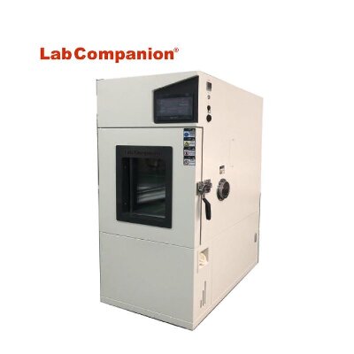
Suitable for various small electrical appliances, instruments, materials, and components for wet heat testing, it is also suitable for conducting aging tests. This test chamber adopts the most reasonable structure and stable and reliable control method currently available, making it aesthetically pleasing, easy to operate, safe, and with high precision in temperature and humidity control. It is an ideal equipment for conducting constant temperature and humidity tests.
(1) The test box body is in the form of an integral structure, with the refrigeration system located at the lower rear of the box and the control system located at the upper part of the test box.
(2) Inside the air duct interlayer at one end of the studio, there are devices such as heaters, refrigeration evaporators, and fan blades distributed; On the left side of the test box, there is a Ø 50 cable hole, and the test box is a single door (stainless steel embedded door handle)
(3) The double-layer high temperature and anti-aging silicone rubber seal can effectively ensure the temperature loss of the test chamber
(4) There are observation windows, frost prevention devices, and switchable lighting fixtures on the box door. The observation window adopts multi-layer hollow tempered glass, and the inner adhesive sheet conductive film is heated and defrosted. The lighting fixtures adopt imported brand Philips lamps, which can effectively observe the experimental changes in the studio from all angles.
The refrigeration cycle of the temperature and humidity control box adopts the reverse Carnot cycle, which consists of two isothermal processes and two adiabatic processes. The process is as follows: the refrigerant is adiabatically compressed to a higher pressure by the compressor, and the work consumed increases the exhaust temperature. Then, the refrigerant exchanges heat with the surrounding medium through the condenser and transfers heat to the surrounding medium. After the refrigerant undergoes adiabatic expansion through the shut-off valve, the temperature of the refrigerant decreases. Finally, the refrigerant absorbs heat from the object at a higher temperature through the evaporator, causing the temperature of the cooled object to decrease. This cycle repeats itself to achieve the goal of cooling down.
The refrigeration system design of this test chamber applies energy regulation technology, which can ensure the normal operation of the refrigeration unit and effectively adjust the energy consumption and refrigeration capacity of the refrigeration system, so as to maintain the refrigeration system in the optimal operating state. By using Balanced Temperature Control (BTC), the control system automatically calculates the output of the heater based on the set temperature point through PID calculation when the refrigeration system is working continuously, ultimately achieving a dynamic balance.
Dear customer:
Hello, our company is a high-quality development team with strong technical strength, providing high-quality products, complete solutions, and excellent technical services to our customers. The main products include walk-in constant temperature and humidity testing chambers, UV accelerated aging testing machines, rapid temperature change testing chambers, walk-in environmental testing chambers, UV aging testers, constant temperature and humidity chambers, etc. Our company adheres to the principle of building a business with integrity, maintaining quality, and striving for progress. With a more determined pace, we continuously climb new heights and contribute to the national automation industry. We welcome new and old customers to confidently choose the products they like. We will serve you wholeheartedly!
Service conditions for high, low temperature, and low pressure test chambers
One of the usage conditions for high, low temperature, and low pressure test chambers: environmental conditions
a、 Temperature: 15 ℃~35 ℃;
b、 Relative humidity: not exceeding 85%;
c、 Atmospheric pressure: 80kPa~106kPa
d、 There is no strong vibration or corrosive gas in the surrounding area;
e、 No direct sunlight exposure or direct radiation from other cold or heat sources;
f、 There is no strong airflow around, and when the surrounding air needs to be forced to flow, the airflow should not be directly blown onto the box;
g、 The influence of magnetic field on the control circuit of the interference free test box in the surrounding area;
h、 There is no high concentration of dust or corrosive substances in the surrounding area.
Condition 2 for the use of high, low temperature, and low pressure test chambers: Power supply conditions
a、 AC voltage: 220V ± 22V or 380V ± 38V;
b、 Frequency: 50HZ ± 0.5HZ
Condition Three for the Use of High, Low Temperature, and Low Pressure Test Chambers: Water Supply Conditions
It is advisable to use tap water or circulating water that meets the following conditions:
a、 Water temperature: not higher than 30 ℃;
b、 Water pressure: 0.1MPa~0.3MPa;
c、 Water quality: meets industrial water standards.
Condition 4 for the use of high, low temperature, and low pressure test chambers: Test load conditions
The load of the test chamber should meet the following conditions every week:
a、 The total mass of the load shall not exceed 80KG per cubic meter within the working chamber volume
b、 The total volume of the load shall not exceed 5/1 of the working chamber volume
c、 On any cross-section perpendicular to the prevailing wind direction, the sum of the load areas should not exceed 3/1 of the cross-sectional area of the working chamber at that location, and the load should not obstruct the flow of airflow when placed.
Dear customer:
Our company has products such as rapid temperature change test chambers, UV accelerated weather resistance testing machines, and temperature and humidity control chambers. You can call our service hotline through our website to learn more about our products. Our pursuit is endless, and we welcome new and old customers to choose their favorite products with confidence. We will be dedicated to serving you!
User selection environment test box must read
1、 Equipment selection criteria
There is currently no exact number of natural environmental factors and induced environmental factors that exist on the surface of the Earth and in the atmosphere, among which there are no less than a dozen factors that have a significant impact on the use and lifespan of engineering products (equipment). Engineers engaged in the study of environmental conditions for engineering products have compiled and summarized the environmental conditions that exist in nature and are induced by human activities into a series of testing standards and specifications to guide the environmental and reliability testing of engineering products. For example, GJB150- the National Military Standard of the People's Republic of China for Environmental Testing of Military Equipment, and GB2423- the National Standard of the People's Republic of China for Environmental Testing of Electrical and Electronic Products, which guides environmental testing of electrical and electronic products. Therefore, the main basis for selecting environmental and reliability testing equipment is the testing specifications and standards of engineering products.
Secondly, in order to standardize the tolerance of environmental testing conditions in experimental equipment and ensure the control accuracy of environmental parameters, national technical supervision agencies and various industrial departments have also formulated a series of calibration regulations for environmental testing equipment and detection instruments. Such as the national standard GB5170 of the People's Republic of China "Basic Parameter Calibration Method for Environmental Testing Equipment of Electrical and Electronic Products", and JJG190-89 "Trial Calibration Regulations for Electric Vibration Test Stand System" issued and implemented by the State Administration of Technical Supervision. These verification regulations are also an important basis for selecting environmental and reliability testing equipment. Testing equipment that does not meet the requirements of these verification regulations is not allowed to be put into use.
2、 Basic principles for equipment selection
The selection of environmental and reliability testing equipment should follow the following five basic principles:
1. Reproducibility of environmental conditions
It is impossible to fully and accurately reproduce the environmental conditions that exist in nature in the laboratory. However, within a certain tolerance range, people can accurately and approximately simulate the external environmental conditions that engineering products undergo during use, storage, transportation, and other processes. This passage can be summarized in engineering language as follows: "The environmental conditions (including platform environment) created by the testing equipment around the tested product should meet the requirements of the environmental conditions and their tolerances specified in the product testing specifications. The temperature box used for military product testing should not only meet the requirements of the national military standards GJB150.3-86 and GJB150.4-86 for different uniformity and temperature control accuracy. Only in this way can the reproducibility of environmental conditions be ensured in environmental testing.
2. Repeatability of environmental conditions
An environmental testing equipment may be used for multiple tests of the same type of product, and a tested engineering product may also be tested in different environmental testing equipment. In order to ensure the comparability of test results obtained for the same product under the same environmental testing conditions specified in the testing specifications, it is necessary to require the environmental conditions provided by the environmental testing equipment to be reproducible. This means that the stress levels (such as thermal stress, vibration stress, electrical stress, etc.) applied by environmental testing equipment to the tested product are consistent with the requirements of the same testing specification.
The repeatability of environmental conditions provided by environmental testing equipment is guaranteed by the national metrological verification department after passing the verification according to the verification regulations formulated by the national technical supervision agency. Therefore, it is necessary to require environmental testing equipment to meet the requirements of various technical indicators and accuracy indicators in the calibration regulations, and to not exceed the time limit specified in the calibration cycle in terms of usage time. If a very common electric vibration table is used, in addition to meeting technical indicators such as excitation force, frequency range, and load capacity, it must also meet the requirements of precision indicators such as lateral vibration ratio, table acceleration uniformity, and harmonic distortion specified in the calibration regulations. Moreover, the service life after each calibration is two years, and after two years, it must be re calibrated and qualified before being put into use.
3. Measurability of environmental condition parameters
The environmental conditions provided by any environmental testing equipment must be observable and controllable. This is not only to limit the environmental parameters within a certain tolerance range and ensure the reproducibility and repeatability of the test conditions, but also necessary for the safety of product testing, in order to prevent damage to the tested product caused by uncontrolled environmental conditions and unnecessary losses. At present, various experimental standards generally require that the accuracy of parameter testing should not be less than one-third of the allowable error under experimental conditions.
4. Exclusion of environmental testing conditions
Every time an environmental or reliability test is conducted, there are strict regulations on the category, magnitude, and tolerance of environmental factors, and non test required environmental factors are excluded from penetrating into it, in order to provide a definite basis for judging and analyzing product failure and fault modes during or after the test. Therefore, it is required that environmental testing equipment not only provide the specified environmental conditions, but also not allow any other environmental stress interference to be added to the tested product. As defined in the verification regulations for electric vibration tables, the table leakage magnetic flux, acceleration signal-to-noise ratio, and total root mean square value ratio of in band and out of band acceleration. The accuracy indicators such as random signal verification and harmonic distortion are all established as verification items to ensure the uniqueness of environmental testing conditions.
5. Safety and reliability of experimental equipment
Environmental testing, especially reliability testing, has a long testing cycle and sometimes targets high-value military products. During the testing process, testing personnel often need to operate, inspect or test around the site. Therefore, it is required that environmental testing equipment must have the characteristics of safe operation, convenient operation, reliable use, and long working life to ensure the normal progress of the testing itself. The various protection, alarm measures, and safety interlock devices of the testing equipment should be complete and reliable to ensure the safety and reliability of the testing personnel, the tested products, and the testing equipment itself.
3、 Selection of Temperature and Humidity Chamber
1. Selection of Capacity
When placing the test product (components, assemblies, parts or whole machine) into a climate chamber for testing, in order to ensure that the atmosphere around the test product can meet the environmental testing conditions specified in the test specifications, the working dimensions of the climate chamber and the overall dimensions of the test product should follow the following regulations:
a) The volume of the tested product (W × D × H) shall not exceed (20-35)% of the effective working space of the test chamber (20% is recommended). For products that generate heat during testing, it is recommended to use no more than 10%.
b) The ratio of the windward cross-sectional area of the tested product to the total area of the test chamber on that section shall not exceed (35-50)% (35% is recommended).
c) The distance between the outer surface of the tested product and the wall of the test chamber should be kept at least 100-150mm (recommended 150mm).
The above three provisions are actually interdependent and unified. Taking a 1 cubic meter cube box as an example, an area ratio of 1: (0.35-0.5) is equivalent to a volume ratio of 1: (0.207-0.354). A distance of 100-150mm from the box wall is equivalent to a volume ratio of 1: (0.343-0.512).
In summary, the working chamber volume of the climate environment test chamber should be at least 3-5 times the external volume of the tested product. The reasons for making such regulations are as follows:
After the test piece is placed in the box, it occupies the smooth channel, and narrowing the channel will lead to an increase in airflow velocity. Accelerate the heat exchange between the airflow and the test piece. This is inconsistent with the reproduction of environmental conditions, as relevant standards stipulate that the air flow velocity around the test specimen in the test chamber should not exceed 1.7m/s for temperature environmental tests, in order to prevent the test specimen and the surrounding atmosphere from generating heat conduction that is not in line with reality. When unloaded, the average wind speed inside the test chamber is 0.6-0.8m/s, not exceeding 1m/s. When the space and area ratio specified in points a) and b) are met, the wind speed in the flow field may increase by (50-100)%, with an average maximum wind speed of (1-1.7) m/s. Meet the requirements specified in the standards. If the volume or windward cross-sectional area of the test piece is increased without restrictions during the experiment, the actual airflow speed during the test will exceed the maximum wind speed specified in the test standard, and the validity of the test results will be questioned.
The accuracy indicators of environmental parameters in the working chamber of the climate chamber, such as temperature, humidity, salt spray settling rate, etc., are all measured under no-load conditions. Once the test piece is placed, it will have an impact on the uniformity of the environmental parameters in the working chamber of the test chamber. The larger the space occupied by the test piece, the more severe this impact will be. Experimental data shows that the temperature difference between the windward and leeward sides in the flow field can reach 3-8 ℃, and in severe cases, it can be as high as 10 ℃ or more. Therefore, it is necessary to meet the requirements of a] and b] as much as possible to ensure the uniformity of environmental parameters around the tested product.
According to the principle of heat conduction, the temperature of the airflow near the box wall is usually 2-3 ℃ different from the temperature at the center of the flow field, and may even reach 5 ℃ at the upper and lower limits of high and low temperatures. The temperature of the box wall differs from the temperature of the flow field near the box wall by 2-3 ℃ (depending on the structure and material of the box wall). The greater the difference between the test temperature and the external atmospheric environment, the greater the temperature difference. Therefore, the space within a distance of 100-150mm from the box wall is unusable.
2. Selection of temperature range
At present, the range of temperature test chambers abroad is generally -73 to+177 ℃, or -70 to+180 ℃. Most domestic manufacturers generally operate at -80 to+130 ℃, -60 to+130 ℃, -40 to+130 ℃, and there are also high temperatures up to 150 ℃. These temperature ranges can usually meet the temperature testing needs of the vast majority of military and civilian products in China. Unless there are special requirements, such as products installed near heat sources such as engines, the upper temperature limit should not be blindly increased. Because the higher the upper limit temperature, the greater the temperature difference between the inside and outside of the box, and the poorer the uniformity of the flow field inside the box. The smaller the available studio size. On the other hand, the higher the upper limit temperature value, the higher the heat resistance requirements for insulation materials (such as glass wool) in the interlayer of the box wall. The higher the requirement for the sealing of the box, the higher the production cost of the box.
3. Selection of humidity range
The humidity indicators given by domestic and foreign environmental test chambers are mostly 20-98% RH or 30-98% RH. If the humid heat test chamber does not have a dehumidification system, the humidity range is 60-98%. This type of test chamber can only perform high humidity tests, but its price is much lower. It is worth noting that the corresponding temperature range or minimum dew point temperature should be indicated after the humidity index. Because relative humidity is directly related to temperature, for the same absolute humidity, the higher the temperature, the lower the relative humidity. For example, if the absolute humidity is 5g/Kg (referring to 5g of water vapor in 1kg of dry air), when the temperature is 29 ℃, the relative humidity is 20% RH, and when the temperature is 6 ℃, the relative humidity is 90% RH. When the temperature drops below 4 ℃ and the relative humidity exceeds 100%, condensation will occur inside the box.
To achieve high temperature and high humidity, simply spray steam or atomized water droplets into the air of the box for humidification. Low temperature and humidity are relatively difficult to control because the absolute humidity at this time is very low, sometimes much lower than the absolute humidity in the atmosphere. It is necessary to dehumidify the air flowing inside the box to make it dry. At present, the vast majority of temperature and humidity chambers both domestically and internationally adopt the principle of refrigeration and dehumidification, which involves adding a set of refrigeration light pipes to the air conditioning room of the chamber. When humid air passes through a cold pipe, its relative humidity will reach 100% RH, as the air saturates and condenses on the light pipe, making the air drier. This dehumidification method theoretically can reach dew point temperatures below zero degrees, but when the surface temperature of the cold spot reaches 0 ℃, the water droplets condensed on the surface of the light pipe will freeze, affecting the heat exchange on the surface of the light pipe and reducing the dehumidification capacity. Also, because the box cannot be completely sealed, humid air from the atmosphere will seep into the box, causing the dew point temperature to rise. On the other hand, the moist air flowing between the light tubes only reaches saturation at the moment of contact with the light tubes (cold spots) and releases water vapor, so this dehumidification method is difficult to keep the dew point temperature inside the box below 0 ℃. The actual minimum dew point temperature achieved is 5-7 ℃. A dew point temperature of 5 ℃ is equivalent to an absolute moisture content of 0.0055g/Kg, corresponding to a relative humidity of 20% RH at a temperature of 30 ℃. If a temperature of 20 ℃ and a relative humidity of 20% RH are required, with a dew point temperature of -3 ℃, it is difficult to use refrigeration for dehumidification, and an air drying system must be selected to achieve it.
4. Selection of control mode
There are two types of temperature and humidity test chambers: constant test chamber and alternating test chamber.
The ordinary high and low temperature test chamber generally refers to a constant high and low temperature test chamber, which is controlled by setting a target temperature and has the ability to automatically maintain a constant temperature to the target temperature point. The control method of the constant temperature and humidity test chamber is also similar, setting a target temperature and humidity point, and the test chamber has the ability to automatically maintain a constant temperature to the target temperature and humidity point. The high and low temperature alternating test chamber has one or more programs for setting high and low temperature changes and cycles. The test chamber has the ability to complete the test process according to the preset curve, and can accurately control the heating and cooling rates within the maximum heating and cooling rate capability range, that is, the heating and cooling rates can be controlled according to the slope of the set curve. Similarly, the high and low temperature alternating humidity test chamber also has preset temperature and humidity curves, and the ability to control them according to the preset. Of course, alternating test chambers have the function of constant test chambers, but the manufacturing cost of alternating test chambers is relatively high because they need to be equipped with curve automatic recording devices, program controllers, and solve problems such as turning on the refrigeration machine when the temperature in the working room is high. Therefore, the price of alternating test chambers is generally more than 20% higher than that of constant test chambers. Therefore, we should take the need for experimental methods as the starting point and choose a constant test chamber or an alternating test chamber.
5. Selection of variable temperature rate
Ordinary high and low temperature test chambers do not have a cooling rate indicator, and the time from the ambient temperature to the nominal lowest temperature is generally 90-120 minutes. The high and low temperature alternating test chamber, as well as the high and low temperature alternating wet heat test chamber, both have temperature change speed requirements. The temperature change speed is generally required to be 1 ℃/min, and the speed can be adjusted within this speed range. The rapid temperature change test chamber has a fast temperature change rate, with heating and cooling rates ranging from 3 ℃/min to 15 ℃/min. In certain temperature ranges, the heating and cooling rates can even reach over 30 ℃/min.
The temperature range of various specifications and speeds of rapid temperature change test chambers is generally the same, that is, -60 to+130 ℃. However, the temperature range for assessing the cooling rate is not the same. According to different test requirements, the temperature range of rapid temperature change test chambers is -55 to+80 ℃, while others are -40 to+80 ℃.
There are two methods for determining the temperature change rate of the rapid temperature change test chamber: one is the average temperature rise and fall rate throughout the entire process, and the other is the linear temperature rise and fall rate (actually the average speed every 5 minutes). The average speed throughout the entire process refers to the ratio of the difference between the highest and lowest temperatures within the temperature range of the test chamber to the time. At present, the technical parameters of temperature change rate provided by various environmental testing equipment manufacturers abroad refer to the average rate throughout the entire process. The linear temperature rise and fall rate refers to the guaranteed temperature change rate within any 5-minute time period. In fact, for the rapid temperature change test chamber, the most difficult and critical stage to ensure the linear temperature rise and fall speed is the cooling rate that the test chamber can achieve during the last 5 minutes of the cooling period. From a certain perspective, the linear heating and cooling speed (average speed every 5 minutes) is more scientific. Therefore, it is best for the experimental equipment to have two parameters: the average temperature rise and fall speed throughout the entire process and the linear temperature rise and fall speed (average speed every 5 minutes). Generally speaking, the linear heating and cooling speed (average speed every 5 minutes) is half of the average heating and cooling speed throughout the entire process.
6. Wind speed
According to relevant standards, the wind speed inside the temperature and humidity chamber during environmental testing should be less than 1.7m/s. For the test itself, the lower the wind speed, the better. If the wind speed is too high, it will accelerate the heat exchange between the surface of the test piece and the airflow inside the chamber, which is not conducive to the authenticity of the test. But in order to ensure uniformity within the testing chamber, it is necessary to have circulating air inside the testing chamber. However, for rapid temperature change test chambers and comprehensive environmental test chambers with multiple factors such as temperature, humidity, and vibration, in order to pursue the rate of temperature change, it is necessary to accelerate the flow velocity of the circulating airflow inside the chamber, usually at a speed of 2-3m/s. Therefore, the wind speed limit varies for different usage purposes.
7. Temperature fluctuation
Temperature fluctuation is a relatively easy parameter to implement, and most test chambers produced by environmental testing equipment manufacturers can actually control temperature fluctuations within a range of ± 0.3 ℃.
8. Uniformity of temperature field
In order to simulate the actual environmental conditions that products experience in nature more accurately, it is necessary to ensure that the surrounding area of the tested product is under the same temperature environment conditions during environmental testing. Therefore, it is necessary to limit the temperature gradient and temperature fluctuation inside the test chamber. In the General Principles of Environmental Test Methods for Military Equipment (GJB150.1-86) of the National Military Standard, it is clearly stipulated that "the temperature of the measurement system near the test sample should be within ± 2 ℃ of the test temperature, and its temperature should not exceed 1 ℃/m or the total maximum value should be 2.2 ℃ (when the test sample is not working).
9. Precision control of humidity
The humidity measurement in the environmental testing chamber mostly adopts the dry wet bulb method. The manufacturing standard GB10586 for environmental testing equipment requires that the relative humidity deviation should be within ± 23% RH. To meet the requirements of humidity control accuracy, the temperature control accuracy of the humidity test chamber is relatively high, and the temperature fluctuation is generally less than ± 0.2 ℃. Otherwise, it will be difficult to meet the requirements for humidity control accuracy.
10. Cooling method selection
If the test chamber is equipped with a refrigeration system, the refrigeration system needs to be cooled. There are two forms of test chambers: air-cooled and water-cooled.
Forced air cooling
Water-cooling
Working conditions
The equipment is easy to install, only need to power on.
The ambient temperature should be lower than 28℃. If the ambient temperature is higher than 28℃, it has a certain impact on the refrigeration effect (preferably with air conditioning), the circulating cooling water system should be configured.
Heat exchange effect
Poor (relative to the water-cooling mode)
Stable, good
Noise
Large (relative to the water-cooling mode)
Less
The walk-in high and low temperature (humid and hot) laboratory also needs maintenance
Reminder: Remember to maintain the walk-in high and low temperature (humid and hot) laboratory as well!
1. The temperature and humidity testing system of the walk-in high and low temperature (humid and hot) laboratory must be operated and maintained by a dedicated person. Strictly follow the operating procedures of the system and avoid others from operating the system illegally.
2. Long term shutdown of the walk-in high and low temperature (humid and hot) laboratory can affect the effective service life of the system. Therefore, the system should be turned on and operated at least once every 10 days; Do not repeatedly stop the system in a short period of time. The number of starts per hour should be less than 5 times, and the time interval between each start stop should not be less than 3 times; Do not open the door of the walk-in temperature and humidity testing system at low temperatures to prevent damage to the door sealing tape.
3. A system usage file should be established to facilitate system maintenance and repair. The use of archives should record the start and end time (date) of each system operation, the type of experiment, and the ambient temperature; When the system malfunctions, provide a detailed description of the fault phenomenon as much as possible; The maintenance and repair of the system should also be recorded in as much detail as possible.
4. Conduct a monthly main power switch (leakage circuit breaker) operation test to ensure that the switch is used as a leakage protector while meeting the load capacity. The specific steps are as follows: first, please confirm that the main power switch is turned to "ON", which means the system is powered on, and then press the test button. If the switch lever of the residual current circuit breaker falls down, this function is normal.
5. The main box of the walk-in temperature and humidity testing system should be protected during use and should not be subjected to strong impacts from sharp or blunt objects.
6. To ensure the normal and clean supply of cooling water, the cooling water filter of the refrigeration unit should be cleaned every 30 days. If the local air quality is poor and the dust content in the air is high, the cooling water tower reservoir should generally be cleaned every 7 days.
7. The leakage, overload, and short-circuit protection characteristics of the residual current switch are set by Lab Companion manufacturer and cannot be adjusted arbitrarily during use to avoid affecting performance; After the leakage switch is disconnected due to a short circuit, the contacts need to be checked. If the main contacts are severely burned or have pits, maintenance is required.
8. The test products placed in the walk-in temperature and humidity testing system should be kept at a certain distance from the suction and exhaust ports of the air conditioning channel to avoid obstructing air circulation.
9. Overtemperature protector action test. Set the temperature of the over temperature protector to be lower than the temperature of the box. If there is an E0.0 alarm and buzzing sound, it indicates that its function is normal. After completing the above experiment, the temperature protection setting should be reset appropriately, otherwise it may cause inappropriate termination.
10. Once a year, use a vacuum cleaner to clean and remove dust from the distribution room and water circuit room. Once a month, use a dry cloth to clean the accumulated water in the water tray of the refrigeration unit.
EC-85MHPM-W, High load corresponding constant temperature and humidity tank (800L)
Project
Type
Series
MHPM-W
Function
Temperature and humidity mode
The way of wet ball
Temperature range
-40 ~ + 100 ℃
Humidity range
20 ~ 98%RH
(According to the anaphase 3 items)
Changes in temperature and humidity
± 0.3 ℃ / ±2.5%RH
Temperature and humidity distribution
± 0.5 ℃ / ±5.0%RH
The temperature drops the time
+20 ~ -40 ℃
Within 75 minutes
Temperature rise time
-40 ~ + 100 ℃
Within 50 minutes
The internal volume of the uterus was tested
800 L
Test room inch method (width, depth and height)
1000mm × 800mm × 1000mm
Product inch method (width, depth and height)
1400mm × 1190mm × 1795mm
Make the material
External outfit
Test room control panel
machine room
Cold steel plate, cold steel plate beige
(Color table 2.5Y8 / 2)
Inside
Stainless steel plate (SUS304,2B polished)
Broken heat material
Test room
Hard synthetic resin
―
Door
Hard synthetic resin foam cotton, glass cotton
Project
Type
Series
MHPM-W
Cooling removal, wet device
Cooling-down method
Mechanical section shrinkage mode
Cooling medium
R404A
The oneself can shrink machine
Output (number of staff)
1.5kW (1)
Cooling and dehumidifier
Multi-channel mixed heat sink type
The condenser
Multi-channel mixed radiator sink (air cooling)
Calorifier
Form
Nickel-chromium heat-resistant alloy heater
Volume
3.5kW
Humidifier
Form
Steam generation
Volume
1.8Kw×2
Blower
Form
Multi-channel mixed radiator sink (air cooling)
Motor capacity
40W
Feed water unit
The water supply cylinder Water supply method
Water quality
Pure water * Automatic water supply
("Please refer to the automatic water supply.")
Volume
Gravity type
Moisturizing disk
Gravity type
Controller
Temperature setting range
-42.0 ~ + 102.0 ℃
Humidity setting range
0 ~ 98%RH (Dry Bulb Temperature 10 ~ 85 ℃ )
Time set range
0 ~ 999Time of 59 min(Program setting type) 0 ~ 20000 Time of 59 min(The value type)
Set decomposition energy
Temperature 0.1℃, humidity 1% RH for 1 min
Indicate accuracy
Temperature ± 0.8℃ (tp.), humidity ± 1% RH (tp.), time ± 100 PPM
Vacation type
Value or program
Stage number
20-stage / 1 program
The number of procedures
The maximum number of incoming force (RAM) programs is 32 programs
The maximum number of internal ROM programs is 13 programs
Round-trip number
98 times maximum or unlimited
Number of round-trip repeats
Maximum 3 heavy
Displace the end
Pt 100Ω ( at 0 ℃ ), grade B( JIS C 1604-1997 )
Control action
When splitting the PID action
Internal function
Early delivery function, standby function, setting value maintenance function, power outage protection function,
Power action selection function, maintenance function, transportation round-trip function,
Time delivery function, time signal output function, overrising and overcooling prevention function,
Abnormal representation function, external alarm output function, setting paradigm representation function,
Transport type selection function, the calculation time represents the function, the slot lamp lamp function
Project
Type
Series
MHPM-W
Control panel
Equipment machine
LCD operating panel (type contact panel),
Represents lamp (power, transport, abnormal), test power supply terminal, external alarm terminal,
Time signal output terminal, power cord connector
Protective device
Refrigerating cycle
Overload protection device, high blocking device
Calorifier
Temperature over-rise protection device, temperature fuse
Humidifier
Air burning prevention device, humidifying disc water level regulator
Blower
Overload protection device
Control panel
Leakage breaker for power supply, fuse (for heater, humidifier),
Fuse (for operating loop), temperature rise protection device (for testing),
Temperature rise overcooling prevention device (test material, in microcomputer)
Offproducts (sets)
House receiver (4), house board (2), wet ball wick (15), operation manual (1)
Equipment products
Adventitia
Hard borosilicate glass 800mm× 800mm
2
Cable hole
Bore size 50mm
1
The trough inside the lamp
AC100V 15W White hot ball
2
Wheel
4
Horizontal adjustment
4
Electrovirus characteristics
Source
AC three-phase 380V 50Hz
Maximum load current
25A
Capacity of the leakage breaker for the power supply
50A
Sensory current 30mA
Power distribution thickness
14mm2
Rubber insulation hose
Coarseness of grounding wire
5.5mm2
Tubing
Drain-pipe
PT1/2
Product quality
550kg
Daily maintenance tips for high and low temperature test chambers and alternating high and low temperature test chambers
1. High and low temperature test chambers are generally relatively high, and we recommend placing them in a relatively benign temperature environment. Our experience temperature value is 8 ℃~23 ℃. For laboratories that do not have this condition, appropriate air conditioners or cooling towers must be equipped.
2. It is necessary to adhere to professional management by dedicated personnel. Units with conditions should periodically send dedicated personnel to the supplier's factory for training and learning, in order to gain more professional experience and ability in maintenance and repair Hongzhan Instrument.
3. Regularly clean the condenser every 3 months: For compressors that use air-cooled cooling, the condenser fan should be regularly inspected and the condenser should be cleaned and dusted to ensure good ventilation and heat transfer performance; For compressors that use water-cooled cooling, in addition to ensuring their inlet water pressure and temperature, it is also necessary to ensure the corresponding flow rate. Regular cleaning and descaling of the condenser interior is also necessary to obtain its continuous heat transfer performance.
4. Regularly clean the evaporator: Due to the different cleanliness levels of the test samples, a lot of small particles such as dust will accumulate on the evaporator under forced air circulation, and should be cleaned regularly.
5. Cleaning and balancing of circulating air blades and condenser fans: Similar to cleaning evaporators, due to the different working environments of the test chamber, many small particles such as dust may accumulate on the circulating air blades and condenser fans, and should be cleaned regularly.
6. Cleaning of waterway and humidifier: If the waterway is not smooth and the humidifier scales, it is easy for the humidifier to dry and burn, which may damage the humidifier. Therefore, it is necessary to regularly clean the waterway and humidifier.
7. After each experiment, set the temperature near the ambient temperature, work for about 30 minutes, then cut off the power and clean the inner wall of the workshop.
If the equipment needs to be relocated, it is best to do so under the guidance of technical personnel from Hongzhan Company to avoid unnecessary damage or damage to the equipment.
When the product is not in use for a long period of time, it should be powered on regularly every half month, and the power on time should not be less than 1 hour.
10. Maintenance principle:
Due to the fact that high and low temperature test chambers are mainly composed of electrical, refrigeration, and mechanical systems, once there is a problem with the equipment, a comprehensive inspection and analysis of the entire equipment system should be carried out.
Generally speaking, the process of analysis and judgment can start with "external" and then "internal", that is, after excluding external factors, the equipment can be systematically decomposed based on the fault phenomenon. Then, the system can be comprehensively analyzed and judged. Alternatively, the reverse reasoning method can be used to find the cause of the fault: first, check whether there is a problem with the electrical system according to the electrical wiring diagram, and finally check whether there is a problem with the refrigeration system. Before understanding the cause of the fault, it is not advisable to disassemble or replace components blindly to avoid unnecessary trouble.
The first natural environment icing test station in China, jointly built by Chongqing University and Huaihua Electric Power Bureau, has settled in Xuefeng Mountain!
On January 16th, the "Xuefengshan Natural Ice Cover Test Station" Insulator Ice Cover Test Technology Exchange Seminar, jointly organized by Chongqing University and Hunan Huaihua Electric Power Design Institute, was held in Huaihua. Experts in transmission and distribution lines and insulation technology from well-known universities across the country, as well as electrical experts from Japan's NGK company, gathered together to celebrate the official completion of the world's only and China's first natural ice cover test station in Huaihua, Hunan, and to discuss follow-up research matters.
At the meeting, Professor Jiang Xingliang, doctoral supervisor of Chongqing University, first expressed gratitude to Huaihua Electric Power Bureau and various units of the power system for their strong support and assistance in the basic design and construction of the experimental base. The attending experts listened to Associate Professor Zhang Zhijin's report on the construction of the Xuefengshan Natural Ice Cover Test Station and the 2009 Ice Cover Test, shared the ice observation and research results at the test base throughout 2009, and conducted in-depth discussions and research on the existing problems. After the meeting, experts also went to the "Xuefengshan Natural Ice Cover Test Station" for on-site investigation, and representatives expressed their affirmation of the site selection and the construction of the test station.
Professor Jiang Xingliang introduced that since the 2008 ice disaster, in order to prevent a large number of line disconnections, tower collapses, and ice flash accidents caused by severe icing, and to maintain the safe and stable operation of the power grid, the Ministry of Science and Technology of China has listed grid icing and protection technology as one of the important research topics of the National Key Basic Research and Development Plan (973 Plan). With the support of projects such as "Ice Cover, De icing, and Melting Mechanisms of Transmission Lines" by State Grid Corporation of China, Professor Jiang Xingliang's research team conducted a comprehensive investigation of typical ice cover conditions in China, analyzed and compared ice cover phenomena and micro meteorology in Liupanshui, Guizhou, Qinling Mountains, Shaanxi, Jingmen, Sichuan, and Lushan, Jiangxi. Based on the representativeness, duration, and transportation conditions of ice cover, it was determined to establish a "natural ice cover test base" in Xuefengshan, Hunan. It was believed that the natural conditions of Pingshantang in Xuefengshan and the technical strength of Huaihua Design Institute met the requirements for the construction of natural ice cover test bases. Finally, the site selection and cooperation partner were determined.
In 2009, Professor Jiang Xingliang, Associate Professor Zhang Zhijin, and Dr. Hu Jianlin, among other key members of the research group, led more than ten graduate students from the Department of High Voltage and Insulation Technology at Chongqing University to overcome various difficulties in work and life under harsh natural conditions. They worked together with the Huaihua Bureau Design Institute to build a natural experimental base while conducting experimental research. In the first year of the experiment, the icing, thawing, and de icing processes of six typical specifications of conductors commonly used in high voltage, ultra-high voltage, and ultra-high voltage transmission lines were studied. The icing processes of various types of insulators were observed and compared. Multiple technical measures to prevent conductor icing, such as mechanical and hydrophobic coatings, as well as coatings to prevent insulator icing and differences in insulator icing arrangements, were experimentally investigated. The twisting process and mechanism of conductor icing were analyzed, and the tension changes and ice wind load changes after conductor icing were analyzed. In addition, AC and DC icing tests were conducted in natural environments. A large amount of key experimental data was accumulated to overcome the world-class problem of power grid icing, and many effective studies and explorations were made.
Toshiyuki Nakajima, Chief Engineer of the Electric Power Division of NGK Corporation in Japan, stated in an interview with reporters during his inspection of the Xuefengshan Natural Ice Cover Test Station that he has been engaged in research on power grid ice cover in the United States for 10 years. Although international experts have conducted long-term research on power grid ice cover under laboratory artificial simulation conditions, they unanimously believe that there is a significant error between the ice cover form in the artificial simulation environment and the actual situation in the natural environment. The first natural ice cover test station built in Xuefengshan will undoubtedly greatly promote the research process of ice cover and melting mechanisms of transmission lines and the anti ice ability of power grids in China and internationally. He wishes his Chinese counterparts to soon obtain the foundation of ice cover on transmission lines in natural environments. Data fills the gap in international research in this field, Overcome the world-class challenge of power grid icing mechanism and anti icing technology as soon as possible.
Zhang Jiwu, President of the Design Institute of Huaihua Electric Power Bureau, stated that with the strong support of Secretary Liang Liqing of the Huaihua Electric Power Bureau Party Committee, the Xuefengshan Natural Ice Cover Test Station has been built in cooperation with Chongqing University. On the one hand, it can make its own contribution to the research on improving the ice resistance of the power grid and reflect the company's sense of social responsibility; On the other hand, it can also enhance its own technological strength and corporate reputation through cooperation and exchange, improve its external competitiveness, and achieve a win-win situation. It is a model of "industry university research" cooperation between enterprises and higher education institutions. (Shu Daisong and Zhang Deming)
Information source: Hunan Electric Power Company
Lab Companion has a research institution specializing in the development of environmental testing equipment, with mature environmental testing research methods and laboratories. It has gathered a group of excellent talents and well-known experts in the industry, and a strong R&D team is leading the development direction of domestic environmental testing technology. At present, the company has independent intellectual property rights in environmental testing equipment, reliability testing equipment, high and low temperature testing chambers, high and low temperature humidity testing chambers, constant temperature and humidity testing chambers, rapid temperature change testing chambers, cold and hot shock testing chambers, three comprehensive testing chambers, high and low temperature and low pressure testing chambers, solar radiation testing chambers, industrial ovens, cold and hot shock testing chambers, walk-in constant temperature and humidity testing chambers, environmental stress screening testing chambers, walk-in constant temperature and humidity testing chambers, high and low temperature impact testing chambers, constant temperature and humidity testing machines, constant temperature and humidity testing chambers, solar radiation testing chambers, high and low temperature humidity testing chambers, temperature and humidity control chambers, UV accelerated aging testing machines, UV accelerated weathering testing machines, walk-in testing chambers, walk-in environmental testing chambers. Room, walk-in high and low temperature laboratory, temperature and humidity control test chamber, UV weather resistance test chamber, UV aging tester, The climate environment testing equipment and customized products, including high, low temperature and low pressure test chambers, rapid temperature cycling test chambers, walk-in constant temperature and humidity test chambers, walk-in high, low temperature and humidity test chambers, precision ovens, programmable constant temperature and humidity test chambers, programmable constant temperature and humidity test machines, xenon lamp aging test chambers, high and low temperature alternating humidity test chambers, constant temperature and humidity test chambers, walk-in high and low temperature humidity test chambers, and high wind speed rain test chambers, are at the forefront of domestic and international standards. Welcome new and old customers to contact us for inquiries. We will be dedicated to serving you!


 Get A Quote


 IPv6 network supported