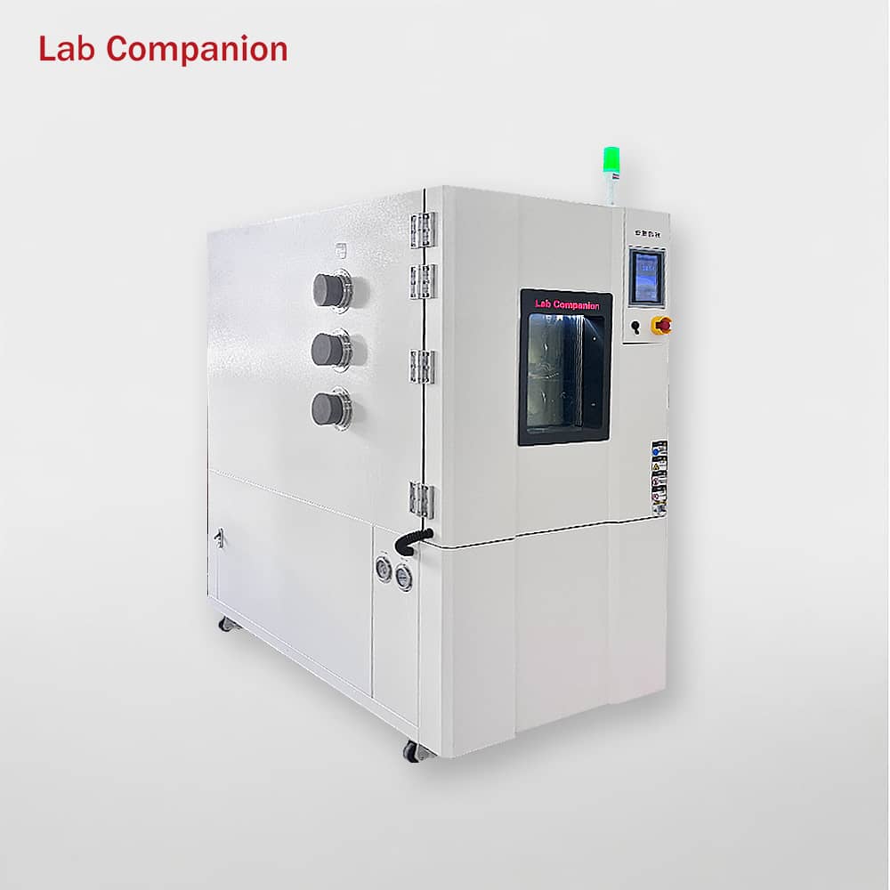
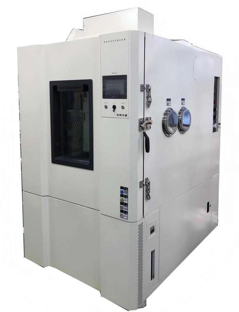
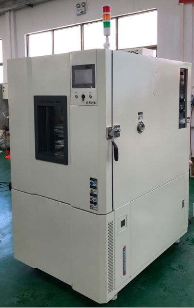
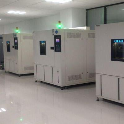
The precise environmental simulation capability of the temperature and humidity test chamber relies on a modular structure design of "chamber base + functional systems + control system". All components work in synergy to achieve accurate regulation and stable maintenance of temperature and humidity. The core structure is divided into the following parts:
I. Chamber Basic Structure: Core of Environmental Bearing
1. Inner Tank: As the core carrier of the test area, it is usually made of SUS 304 stainless steel for excellent corrosion resistance and easy cleaning. The smooth inner wall is equipped with one or two axial fans (quantity depends on test chamber volume), which circulate air inside the chamber to ensure uniform airflow distribution. For some models, the inner tank is treated with anti-condensation technology to prevent water dripping from affecting test results.
2. Outer Shell: Mainly constructed from galvanized steel sheets with electrostatic powder coating, it serves as protection and thermal insulation. The gap between the outer shell and inner tank is filled with dense mineral wool to minimize heat exchange between the inside and outside of the chamber, reducing energy consumption.
3. Chamber Door & Door Seal: The door is fitted with multi-layer heated glass, which allows real-time observation of test status; the heating and defrosting function prevents glass fogging. A silicone door seal is attached to the inner side of the door to ensure airtightness and avoid temperature/humidity leakage.
4. Shelves: Height-adjustable stainless steel shelves are designed for placing test samples. They ensure unobstructed air circulation around samples and do not interfere with internal airflow.
II. Temperature Control System
1. Heating Assembly: Installed near the air duct of the inner tank, it features electric heating tubes as the core component. With high temperature resistance and uniform heat generation, the tubes directly supply heat to the internal air and respond to heating commands from the controller.
2. Refrigeration System: Air conditioning components are integrated into the air handling system at the rear of the test chamber. Circulating air is cooled when passing through a heat exchanger. The condenser is generally air-cooled, with a water-cooled option available.
III. Humidity Control System
A. Humidification Device
l Electrode-type Humidifier: Consists of electrode rods and a humidification water tank (for storing distilled/deionized water). Steam is generated by heating the water when the electrode rods are energized.
B. Dehumidification Device
l Refrigeration Dehumidification Module: Linked with the evaporator, it achieves dehumidification through cooling and condensation.
l Drainage PipeCollects condensed water and discharges it outside the chamber to maintain inner tank dryness.
IV. Operation & Control System
1. Operators can send commands to the Labcompanion controller via the color LCD touchscreen to control the test chamber. Intuitive graphic symbols enable a user-friendly interface, simplifying operation without requiring additional instructions.
2. The Labcompanion controller is a self-monitoring, 32-bit digital measurement and control system specifically designed for test system applications.
Key Features
l Height-adjustable color LCD touchscreen for flexible operation.
l The program memory can store 100 test programs, with a total of up to 1000 program steps, supporting 250 program step cycles and 9999 program cycles.
l Software supports non-voltage input/output switches.
l Integrated temperature and humidity limit monitoring system.
l Connectable to host server systems via RS232-C serial interface or to network systems via TCP/IP.
l Switchable Chinese/English interface.
In summary, the structural design of the test chamber is centered on precision control, stable operation and reliability, with all components corresponding to the temperature/humidity control principles. Understanding the core components facilitates efficient equipment maintenance and troubleshooting.
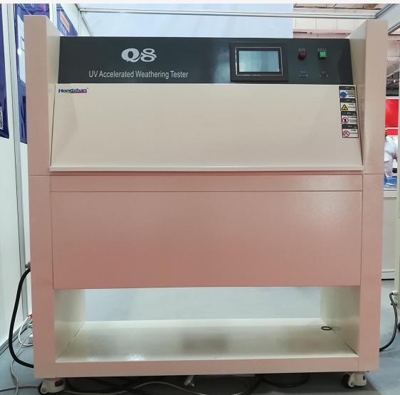
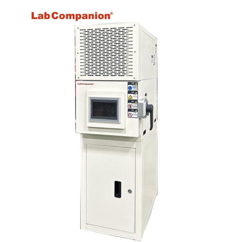
Lab Companion UV weathering test chamber is a professional device used to simulate and evaluate the resistance performance of materials under ultraviolet radiation and corresponding climatic conditions for testing outdoor products. Its core function lies in simulating the impact of ultraviolet rays on materials in the natural environment through artificially controlled ultraviolet irradiation, temperature and humidity changes, thereby conducting comprehensive and systematic tests on the durability, color stability and physical properties of materials. In recent years, with the development of technology and the continuous improvement of requirements for material performance, the application of UV weathering test chambers has become increasingly widespread, covering multiple fields such as plastics, coatings, and textiles.
The Q8 system independently developed by Lab can simulate the damage caused by sunlight and rain, and complies with multiple international certification standards. It can be programmed to conduct continuous ultraviolet light and rain weather resistance tests 24 hours a day and 7 days a week. It only takes a few days or weeks to reproduce the damage that occurs outdoors in months or even years, including various phenomena such as color change and powdering. Meanwhile, the Q8/UV2/UV3 are equipped with a standard ultraviolet light detection system, which precisely controls the light intensity. Four sets of UV intensity sensors automatically adjust the energy of the lamp tubes based on the aging state to make compensation, significantly reducing the experimental time and ensuring the reproducibility of the system.
To more realistically simulate the effects of rainwater scouring and cooling, the ultraviolet test chamber is also equipped with a spray system. The Q8/UV3 model is equipped with 12 sets of water spray devices to simulate mechanical corrosion caused by rainwater erosion. When the sample is heated to a high temperature by an ultraviolet lamp, it is sprayed with cold water to generate intense thermal contraction stress, simulating a sudden downpour in summer. The scouring effect of water flow can simulate the erosion of coatings, paints and other surfaces by rainwater, washing away the aged and decomposed substances on the surface and exposing new material layers to continue aging.
A typical test loop is:
Under the set irradiance and high temperature, 4 hours of ultraviolet light is used to simulate daytime sun exposure. With the lights off and high humidity maintained, 4 hours of condensation at night is simulated. During this process, short sprays can be inserted regularly to simulate rainfall.
By intensifying and cycling these key environmental factors, the ultraviolet light test chamber can reproduce within days or weeks the aging damage that materials would take months or even years outdoors, thus being used for product quality control and durability assessment. However, this test is an accelerated experiment, and its results are correlated with those of real outdoor exposure, rather than being completely equivalent. Different materials and testing standards will select different types of lamp tubes, irradiance, temperatures, and cycle periods to obtain the most relevant prediction results.
The Measuring Principle of Hygrometer in High and Low Temperature Test Chamber
Temperature and humidity is the percentage of the amount of water vapor (vapor pressure) contained in a gas (usually air) and the amount of saturated water vapor (saturated vapor pressure) in the same case as the air, expressed in RH%. Humidity long ago had a close relationship with life, but it was difficult to quantify it. The expression of humidity is humidity, relative humidity, dew point, ratio of moisture to dry gas (weight or volume), and so on.
Humidity measurement method hygrograph humidity measurement from the principle of the division of twenty or thirty. But humidity measurement is always one of the difficult problems in the world measurement field. A seemingly simple quantity value, in depth, involves quite complex physico-chemical theoretical analysis and calculation, beginners may ignore many factors that must be paid attention to in humidity measurement, thus affecting the reasonable use of sensors.
Common humidity measurement methods are: dew point method, wet and dry bulb method and electronic sensor method, dynamic method (double pressure method, double temperature method, shunt method), static method (saturated salt method, sulfuric acid method)
1, Dew point method hygrograph: is to measure the temperature when the wet air reaches saturation, is a direct result of thermodynamics, high accuracy, wide measurement range. Precision dew point instrument for measurement can reach ±0.2°C or even higher accuracy. However, the cold mirror dew-point meter with modern optoelectric principle is expensive and often used with standard humidity generators.
2, Wet and dry bulb hygrometer: this is a wet measurement method invented in the 18th century. It has a long history and is widely used. Wet and dry bulb method is an indirect method, which converts the humidity value from the wet and dry bulb equation, and this equation is conditional: that is, the wind speed near the wet bulb must reach more than 2.5m/s. The common wet and dry bulb thermometer simplifies this condition, so its accuracy is only 5~7%RH, and the wet and dry bulb does not belong to the static method, do not simply think that improving the measurement accuracy of the two thermometers is equal to improving the measurement accuracy of the hygrometer.
3, Electronic humidity sensor method hygrometer: electronic humidity sensor products and humidity measurement belong to the industry that rose in the 1990s in recent years, at home and abroad in the field of humidity sensor research and development has made great progress. Humidity sensors are developing rapidly from simple humidity sensors to integrated, intelligent, multi-parameter detection, creating favorable conditions for the development of a new generation of humidity measurement and control systems, and also raising humidity measurement technology to a new level.
4, Double pressure method, double temperature hygrometer: is based on the thermodynamic P, V, T balance principle, the balance time is longer, shunt method is based on the precise mixing of moisture and dry air. Due to the use of modern measurement and control means, these devices can be quite precise, but because of the complex equipment, expensive, time-consuming operation, mainly used as standard measurement, its measurement accuracy can reach ±2%RH or more.
5, Static method of saturated salt hygrometer: is a common method in humidity measurement, simple and easy. However, the saturated salt method has strict requirements for the balance of liquid and gas two phases, and high requirements for the stability of ambient temperature. It requires a long time to balance, and low humidity points require even longer. Especially when the humidity difference between the indoor and the bottle is large, it needs to be balanced for 6 to 8 hours each time it is opened.
Display and Heating System of Temperature and Humidity Test Chamber
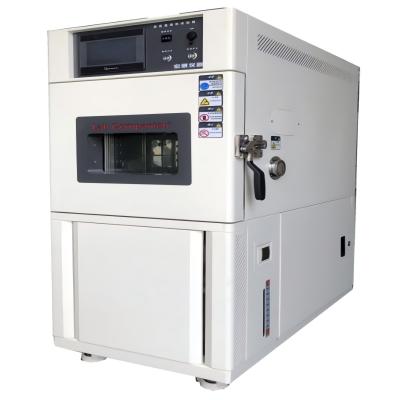
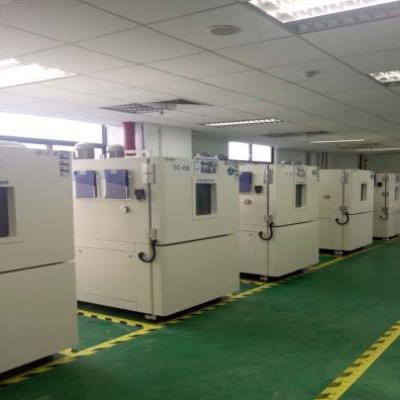
The display and control interface of temperature and humidity test chamber is intuitive and clear, and the light touch selection menu is simple and easy to use, and the performance is stable and reliable. Flexible program control, to bring users stable performance, flexible control, cost-effective products. The input channel and output channel can be expanded arbitrarily. It is a test equipment for aviation, automotive, home appliances, scientific research and other fields, used to test and determine the parameters and performance of electrical, electronic and other products and materials after temperature environment changes in high temperature, low temperature, alternating temperature and humidity degree or constant test.
Product features:
1, Use CNC cutting, laser opening, mass production test chamber.
2, Spray strictly use outdoor powder, powder is not recycled once use, strong adhesion without variegation.
3, The visual window frame is made of one-time opening mold, which has a strong industrial sense.
4, The instrument panel made of one-time mold is beautiful and generous. The label on the instrument panel uses PVC stickers and the back glue uses 3M glue.
5, The caster adopts the free adjustment height caster made by Qidong Baiyun Electronics original factory, non-market counterfeit products, high quality, beautiful and generous.
6, All the standard drawings of the refrigeration system are welded to ensure that the piping of each equipment is consistent, and the refrigeration performance has reached the appropriate state.
7, Wiring of all the standard drawings of the electrical system, thirteen inspection processes after the completion of wiring to ensure accurate wiring and no trouble.
8, The water system uses three cups to control the water level to ensure that the humidifier water supply is separated from the wet bulb water level. The temperature fluctuation caused by humidifier water is avoided.
Display:
1, The original brand temperature and humidity meter, 5.7-inch high-definition true color LCD touch screen.
2, Real-time monitoring (monitoring controller real-time data, signal point status, actual output status).
3, The controller can store the historical data within 600 days (when the temperature and humidity data are recorded at the same time at a recording interval of more than 1 minute in 24-hour operation), and can play back the uploaded historical data curve.
4, The exported files can be viewed on the computer or converted into EXCEL format by random gift software.
5, Instrument equipped with RS232/485 port.
6, With automatic calculation function, the temperature and humidity change conditions can be corrected immediately, so that the temperature and humidity control is more safe and stable.
Heating system:
1, The use of far infrared nickel alloy high-speed heating (2KW×2) electric heater;
2, High temperature independent system, does not affect low temperature test, high temperature test and alternating temperature and humidity;
3, Temperature and humidity control output power is calculated by microcomputer to achieve high precision and high efficiency.
Operation Precautions of Constant Temperature and Humidity Test Chamber
1, In order to avoid machine failure in the constant temperature and humidity test chamber, please provide power supply within the rated voltage range.
2, In order to prevent electric shock or misoperation and failure, do not switch on the power supply before the installation and wiring is finished.
3, This product is a non-explosion-proof product, please do not use the constant temperature and humidity machine in the environment with flammable or explosive gas.
4, Please try not to open the test chamber door during the work of the instrument, open at high temperature may cause hot injury to the operator, open at low temperature may cause freezing injury to the staff, and may cause freezing of the evaporator, affecting the refrigeration effect. If you must open, please do some protective work,
5, It is prohibited to disassemble, process, transform or repair the constant temperature and humidity machine without permission, otherwise there will be abnormal action, electric shock or fire risk.
6, The chamber's ventilation holes should be kept unobstructed to avoid failure, abnormal operation, reduced life and fire.
7. If the machine is damaged or deformed when unpacking, please do not use it.
8, The machine installation and setting should be careful not to let dust, wire, iron filings or other things into, otherwise wrong action or failure will occur.
9, Wiring must be correct, must be grounded. Non-grounding may cause electric shock, misoperation accidents, abnormal display or large measurement errors.
10, Regularly check the terminal screws and fixed frame, please do not use in the case of loose.
11, During the operation of the instrument, the power input terminal cover must be installed on the terminal board to prevent electric shock.
12, The instrument in operation, modify the setting, signal output, start, stop and other operations, should be fully considered before the safety, wrong operation will cause damage to the working equipment or failure.
13, Please use a dry cloth to wipe the instrument, do not use alcohol, gasoline or other organic solvents, do not splash water on the instrument, if the instrument is immersed in water, please stop use immediately, otherwise there is the risk of leakage, electric shock or fire.
14, The internal parts of the instrument have a certain life period, in order to continue to use the instrument safely, please carry out regular maintenance and maintenance. When scrapping this product, please treat it as industrial waste.
15, Before starting to check whether the power supply is stable.
Use Principle of High and Low Temperature Test Chamber Low Temperature and Constant Temperature Tank
Because of its own circulation system, the uniformity of temperature field is very high, and more and more experiments are applied to the low temperature constant temperature tank. Mainly used in petroleum, chemical, electronic instrumentation, physics, chemistry, biological engineering, medicine and health, life science, light industrial food, physical property testing and chemical analysis and other research departments, colleges and universities, enterprise quality inspection and production departments, to provide users with a hot and cold controlled, uniform and constant temperature field source for test samples or products to perform constant temperature test or test. It can also be used as a heat source or cold source for direct heating or cooling and auxiliary heating or cooling.
What are the precautions for using a low temperature or constant temperature tank?
1, Before the use of low temperature constant temperature tank, the tank should be added to the liquid medium (pure water, alcohol, methyl silicone oil), the medium liquid level should be less than 20mm workbench, otherwise the power will damage the heater.
2, The selection of liquid medium in the low temperature constant temperature tank should comply with the following principles:
When the operating temperature is below 5 ° C, the liquid medium is generally alcohol;
When the operating temperature is 5 ~ 85℃, the liquid medium is generally water;
When the working temperature is 85 ~ 95℃, the liquid medium can choose 15% glycerol aqueous solution, which can reduce the evaporation of water;
When the operating temperature is higher than 95 ° C, oil is generally selected as the liquid medium, and the open cup flash point value of the selected oil should be higher than the operating temperature of 50 ° C or more; Generally, methyl silicone oil with low viscosity is used.
3, Power supply: 220V50Hz, the power supply should be greater than the total power of the instrument, the power supply must have a good "grounding" device.
4, The instrument should be placed in a dry and ventilated place, and there are no obstacles within 300mm around the instrument.
5, When the thermostat working temperature is high, should be careful not to open the cover, hands do not enter the groove, to prevent hot injury.
6, After using, all switches are placed in the off state, cut off the power.
7, Avoid acid and alkali substances into the tank corrosion coil and inner liner.
8, The instrument should do a good job of regular cleaning work, long-term use, empty the media in the tank, and wipe clean, keep the workbench and the operating panel clean.
9, Often pay attention to observe the liquid level in the tank, when the liquid level is too low, the liquid medium should be added in time.
10, Liquid external circulation, customers should pay special attention to the fastness of the connection of the leading pipe, strictly prevent falling off, so as to avoid liquid leakage.
What are the Types of PCB Environmental Tests?
High acceleration test:
Accelerated tests include high accelerated life test (HALT) and High accelerated Stress screening (HASS). These tests assess the reliability of products in controlled environments, including high temperature, high humidity, and vibration/shock tests when the equipment is powered on. The goal is to simulate the conditions that could lead to the imminent failure of a new product. During testing, the product is monitored in a simulated environment. Environmental testing of electronic products usually involves testing in a small environmental chamber.
Humidity and corrosion:
Many PCBS will be deployed in wet environments, so a common test for PCB reliability is a water absorption test. In this type of test, the PCB is weighed before and after being placed in a humidity controlled environmental chamber. Any water adsorbent on the board will increase the weight of the board, and any significant change in weight will result in disqualification.
When performing these tests during operation, exposed conductors should not be corroded in a humid environment. Copper oxidizes easily when it reaches a certain potential, which is why exposed copper is often plated with an antioxidant alloy. Some examples include ENIG, ENIPIG, HASL, nickel gold, and nickel.
Thermal shock and circulation:
Heat testing is usually performed separately from humidity testing. These tests include repeatedly changing the board temperature and checking how thermal expansion/contraction affects reliability. In thermal shock testing, the circuit board uses a two-chamber system to quickly move between two temperature extremes. The low temperature is usually below the freezing point, and the high temperature is usually higher than the glass transition temperature of the substrate (above ~130 ° C). The thermal cycle is carried out using a single chamber, with the temperature changing from one extreme to the other at a rate of 10°C per minute.
In both tests, the board expands or contracts as the board temperature changes. During the expansion process, conductors and solder joints are subjected to high stress, which speeds up the service life of the product and enables the identification of mechanical failure points.
Hydrogen Fuel Cell Environmental Simulation Test Scheme
At present, the economic development model based on the consumption of non-renewable energy based on coal, oil and natural gas has led to increasingly prominent environmental pollution and greenhouse effect. In order to achieve sustainable development of human beings, a harmonious relationship between man and nature has been established. The development of sustainable green energy has become a subject of great concern in the world.
As a clean energy that can store waste energy and promote the transformation from traditional fossil energy to green energy, hydrogen energy has an energy density (140MJ/kg) that is 3 times that of oil and 4.5 times that of coal, and is regarded as a subversive technological direction of the future energy revolution. Hydrogen fuel cell is the key carrier to realize the conversion of hydrogen energy into electric energy utilization. After the goal of carbon neutrality and carbon peak "double carbon" was proposed, it has gained new attention in basic research and industrial application.
Hydrogen fuel cell environmental test chamber of Lab Companion meets: fuel cell stack and module: 1W~8KW, fuel cell engine :30KW~150KW Low temperature cold start test: -40~0℃ Low temperature storage test: -40~0℃ High temperature storage test: 0~100℃.
Introduction of hydrogen fuel cell environmental test chamber
The product adopts functional modular design, explosion-proof and anti-static, and meets the relevant test standards. The product has the characteristics of high reliability and comprehensive safety warning, which is suitable for the test of the reactor and fuel cell engine system. Applicable power up to 150KW fuel cell system, low temperature test (storage, starting, performance), high temperature test (storage, starting, performance), wet heat test (high temperature and humidity
Safety parts:
1. Explosion-proof camera: real-time record the complete test situation in the box, easy to optimize or adjust in time.
2. Uv flame detector: high-speed, accurate and intelligent fire detector, accurate identification of flame signals.
3. Emergency air exhaust outlet: exhaust the toxic combustible gas in the box to ensure the safety of the test.
4. Gas detection and alarm system: intelligent and rapid identification of combustible gas, automatically generate alarm signals.
5. Double parallel single-pole screw mechanism cold unit: It has the characteristics of classification function, large power, small footprint and so on.
6. Gas precooling system: quickly control the gas temperature requirements to ensure cold start conditions.
7. Stack test rack: stainless steel stack test rack, equipped with water cooling auxiliary cooling system.
Fuel cell system test project
Fuel cell system test project
Fuel cell engine air tightness test
Power generation system quality
The volume of the battery stack
Insulation resistance detection
Starting characteristic test
Rated power starting test
Steady-state characteristic test
Rated power characteristic test
Peak power characteristic test
Dynamic response characteristic test
High temperature adaptability test
Fuel cell engine system performance test
Vibration resistance test
Low temperature adaptability test
Starting test (low temperature)
Power generation performance test
Shutdown test
Low temperature storage test
Low temperature start-up and operation procedures
/
/
Reactor and module test items
Reactor and module test items
Routine inspection
Gas leakage test
Normal operation test
Allow working pressure test
Pressure test of cooling system
Gas channeling test
Impact and vibration resistance tests
Electrical overload test
Dielectric strength test
Pressure difference test
Flammable gas concentration test
Overpressure test
Hydrogen leakage test
Freezing/thawing cycle test
High temperature storage test
Air tightness test
Fuel starvation test
Oxygen/oxidizer deficiency test
Short-circuit test
Lack of cooling/impaired cooling test
Penetration monitoring system test
Ground test
Starting test
Power generation performance test
Shutdown test
Low temperature storage test
Low temperature starting test
Product applicable standards:
GB/T 10592-2008 High and low temperature test chamber technical conditions
GB/T 10586-2006 Humidity test chamber technical conditions
GB/T31467.3-2015
GB/T31485-2015
GB/T2423.1-2208
GB/T2423.2-2008
GB/T2423.3-2006
GB/T2523.4-2008
IEC 61646 Test Standard for Thin-film Solar Photoelectric Modules
Through the diagnostic measurement, electrical measurement, irradiation test, environmental test, mechanical test five types of test and inspection mode, confirm the design confirmation and form approval requirements of thin film solar energy, and confirm that the module can operate in the general climate environment required by the specification for a long time.
IEC 61646-10.1 Visual inspection procedure
Objective: To check for any visual defects in the module.
Performance at STC under IEC 61646-10.2 Standard test conditions
Objective: Using natural light or A class simulator, under standard test conditions (battery temperature: 25±2℃, irradiance: 1000wm^-2, standard solar spectrum irradiation distribution in accordance with IEC891), test the electrical performance of the module with load change.
IEC 61646-10.3 Insulation test
Objective: To test whether there is good insulation between the current carrying parts and the frame of the module
IEC 61646-10.4 Measurement of temperature coefficients
Objective: To test the current temperature coefficient and voltage temperature coefficient in the module test. The temperature coefficient measured is valid only for the irradiation used in the test. For linear modules, it is valid within ±30% of this irradiation. This procedure is in addition to IEC891, which specifies the measurement of these coefficients from individual cells in a representative batch. The temperature coefficient of the thin-film solar cell module depends on the heat treatment process of the module involved. When the temperature coefficient is involved, the conditions of the thermal test and the irradiation results of the process should be indicated.
IEC 61646-10.5 Measurement of nominal operating cell temperature (NOCT)
Objective: To test the NOCT of the module
IEC 61646-10.6 Performance at NOCT
Objective: When the nominal operating battery temperature and irradiance are 800Wm^-2, under the standard solar spectrum irradiance distribution condition, the electrical performance of the module varies with the load.
IEC 61646-10.7 Performance at low irradiance
Objective: To determine the electrical performance of modules under load under natural light or A class A simulator at 25℃ and 200Wm^-2(measured with appropriate reference cell).
IEC 61646-10.8 Outdoor exposure Testing
Objective: To make an unknown assessment of the resistance of the module to exposure to outdoor conditions and to show any effects of degradation that could not be detected by the experiment or test.
IEC 61646-10.9 Hot spot test
Objective: To determine the ability of the module to withstand thermal effects, such as packaging material aging, battery cracking, internal connection failure, local shading or stained edges can cause such defects.
IEC 61646-10.10 UV test (UV test)
Objective: To confirm the ability of the module to withstand ultraviolet (UV) radiation, the new UV test is described in IEC1345, and if necessary, the module should be exposed to light before performing this test.
IEC61646-10.11 Thermal cycling Test (Thermal cycling)
Objective: To confirm the ability of the module to resist thermal inhomogeneity, fatigue and other stresses due to repeated temperature changes. The module should be annealed before receiving this test. [Pre-I-V test] refers to the test after annealing, be careful not to expose the module to light before the final I-V test.
Test requirements:
a. Instruments to monitor the electrical continuity within each module throughout the test process
b. Monitor the insulation integrity between one of the recessed ends of each module and the frame or support frame
c. Record module temperature throughout the test and monitor any open circuit or ground failure that may occur (no intermittent open circuit or ground failure during the test).
d.The insulation resistance shall meet the same requirements as the initial measurement
IEC 61646-10.12 Humidity freeze cycle test
Purpose: To test the module's resistance to the influence of the subsequent sub-zero temperature under high temperature and humidity, this is not a thermal shock test, before receiving the test, the module should be annealed and subjected to a thermal cycle test, [[Pre-I-V test] refers to the thermal cycle after the test, be careful not to expose the module to light before the final I-V test.
Test requirements:
a. Instruments to monitor the electrical continuity within each module throughout the test process
b. Monitor the insulation integrity between one of the recessed ends of each module and the frame or support frame
c. Record module temperature throughout the test and monitor any open circuit or ground failure that may occur (no intermittent open circuit or ground failure during the test).
d. The insulation resistance shall meet the same requirements as the initial measurement
IEC 61646-10.13 Damp heat Test (Damp heat)
Objective: To test the ability of the module to resist long-term infiltration of moisture
Test requirements: The insulation resistance shall meet the same requirements as the initial measurement
IEC 61646-10.14 Robustness of terminations
Objective: To determine whether the attachment between the lead end and the lead end to the module body can withstand the force during normal installation and operation.
IEC 61646-10.15 Twist Test
Objective: To detect possible problems caused by module installation on an imperfect structure
IEC 61646-10.16 Mechanical load test
Purpose: The purpose of this test is to determine the ability of the module to withstand wind, snow, ice, or static loads
IEC 61646-10.17 Hail test
Objective: To verify the impact resistance of the module to hail
IEC 61646-10.18 Light soaking Test
Objective: To stabilize the electrical properties of thin film modules by simulating solar irradiation
IEC 61646-10.19 Annealing Tests (Annealing)
Objective: The film module is annealed before the verification test. If not annealed, the heating during the subsequent test procedure may mask the attenuation caused by other causes.
IEC 61646-10.20 Wet leakage current Test
Purpose: To evaluate the insulation of the module under wet operating conditions and to verify that moisture from rain, fog, dew or melting snow does not enter the live parts of the module circuit, which may cause corrosion, ground failure or safety hazards.
Comparison of Natural Convection Test Chamber, Constant Temperature and Humidity Test Chamber and High Temperature Oven
Instructions:
Home entertainment audio-visual equipment and automotive electronics are one of the key products of many manufacturers, and the product in the development process must simulate the adaptability of the product to temperature and electronic characteristics at different temperatures. However, when using a general oven or thermal and humidity chamber to simulate the temperature environment, either the oven or thermal and humidity chamber has a test area equipped with a circulating fan, so there will be wind speed problems in the test area.
During the test, the temperature uniformity is balanced by rotating the circulating fan. Although the temperature uniformity of the test area can be achieved through the wind circulation, the heat of the product to be tested will also be taken away by the circulating air, which will be significantly inconsistent with the actual product in the wind-free use environment (such as the living room, indoor).
Because of the relationship of wind circulation, the temperature difference of the product to be tested will be nearly 10℃. In order to simulate the actual use of environmental conditions, many people will misunderstand that only the test chamber can produce temperature (such as: oven, constant temperature humidity chamber) can carry out natural convection test. In fact, this is not the case. In the specification, there are special requirements for wind speed, and a test environment without wind speed is required. Through the natural convection test equipment and software, the temperature environment without passing through the fan (natural convection) is generated, and the test integration test is performed for the temperature detection of the product under test. This solution can be used for home related electronics or real-world ambient temperature testing in confined Spaces (e.g., large LCD TV, car cockpits, automotive electronics, laptops, desktops, game consoles, stereos, etc.).
Unforced air circulation test specification :IEC-68-2-2, GB2423.2, GB2423.2-89 3.31 The difference between the test environment with or without wind circulation and the test of products to be tested:
Instructions:
If the product to be tested is not energized, the product to be tested will not heat itself, its heat source only absorbs the air heat in the test furnace, and if the product to be tested is energized and heated, the wind circulation in the test furnace will take away the heat of the product to be tested. Every 1 meter increase in wind speed, its heat will be reduced by about 10%. Suppose to simulate the temperature characteristics of electronic products in an indoor environment without air conditioning. If an oven or a constant temperature humidifier is used to simulate 35 °C, although the environment can be controlled within 35 °C through electric heating and compressor, the wind circulation of the oven and the thermal and humidify test chamber will take away the heat of the product to be tested. So that the actual temperature of the product to be tested is lower than the temperature under the real windless state. It is necessary to use a natural convection test chamber without wind speed to effectively simulate the actual windless environment (indoor, no starting car cockpit, instrument chassis, outdoor waterproof chamber... Such environment).
Comparison table of wind speed and IC product to be tested:
Description: When the ambient wind speed is faster, the IC surface temperature will also take away the IC surface heat due to the wind cycle, resulting in the faster the wind speed and the lower the temperature.


 Get A Quote


 IPv6 network supported