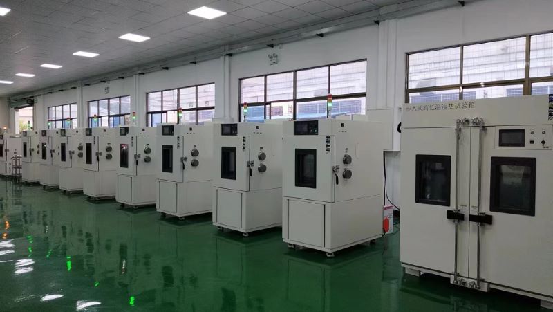
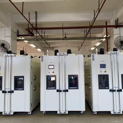
Display and Heating System of Temperature and Humidity Test Chamber
The display and control interface of temperature and humidity test chamber is intuitive and clear, and the light touch selection menu is simple and easy to use, and the performance is stable and reliable. Flexible program control, to bring users stable performance, flexible control, cost-effective products. The input channel and output channel can be expanded arbitrarily. It is a test equipment for aviation, automotive, home appliances, scientific research and other fields, used to test and determine the parameters and performance of electrical, electronic and other products and materials after temperature environment changes in high temperature, low temperature, alternating temperature and humidity degree or constant test.
Product features:
1, Use CNC cutting, laser opening, mass production test chamber.
2, Spray strictly use outdoor powder, powder is not recycled once use, strong adhesion without variegation.
3, The visual window frame is made of one-time opening mold, which has a strong industrial sense.
4, The instrument panel made of one-time mold is beautiful and generous. The label on the instrument panel uses PVC stickers and the back glue uses 3M glue.
5, The caster adopts the free adjustment height caster made by Qidong Baiyun Electronics original factory, non-market counterfeit products, high quality, beautiful and generous.
6, All the standard drawings of the refrigeration system are welded to ensure that the piping of each equipment is consistent, and the refrigeration performance has reached the appropriate state.
7, Wiring of all the standard drawings of the electrical system, thirteen inspection processes after the completion of wiring to ensure accurate wiring and no trouble.
8, The water system uses three cups to control the water level to ensure that the humidifier water supply is separated from the wet bulb water level. The temperature fluctuation caused by humidifier water is avoided.
Display:
1, The original brand temperature and humidity meter, 5.7-inch high-definition true color LCD touch screen.
2, Real-time monitoring (monitoring controller real-time data, signal point status, actual output status).
3, The controller can store the historical data within 600 days (when the temperature and humidity data are recorded at the same time at a recording interval of more than 1 minute in 24-hour operation), and can play back the uploaded historical data curve.
4, The exported files can be viewed on the computer or converted into EXCEL format by random gift software.
5, Instrument equipped with RS232/485 port.
6, With automatic calculation function, the temperature and humidity change conditions can be corrected immediately, so that the temperature and humidity control is more safe and stable.
Heating system:
1, The use of far infrared nickel alloy high-speed heating (2KW×2) electric heater;
2, High temperature independent system, does not affect low temperature test, high temperature test and alternating temperature and humidity;
3, Temperature and humidity control output power is calculated by microcomputer to achieve high precision and high efficiency.
Natural Convection Test (No Wind Circulation Temperature Test) and Specification
Home entertainment audio-visual equipment and automotive electronics are one of the key products of many manufacturers, and the product in the development process must simulate the adaptability of the product to temperature and electronic characteristics at different temperatures. However, when the general oven or constant temperature and humidity test chamber is used to simulate the temperature environment, both the oven and constant temperature and humidity test chamber have a test area equipped with a circulating fan, so there will be wind speed problems in the test area. During the test, the temperature uniformity is balanced by rotating the circulating fan. Although the temperature uniformity of the test area can be achieved through the wind circulation, the heat of the product to be tested will also be taken away by the circulating air, which will be significantly inconsistent with the actual product in the wind-free use environment (such as the living room, indoor). Because of the relationship of wind circulation, the temperature difference of the product to be tested will be nearly 10 ° C, in order to simulate the actual use of environmental conditions, many people will misunderstand that only the test machine can produce temperature (such as: oven, constant temperature and humidity test chamber) can carry out natural convection test, in fact, this is not the case. In the specification, there are special requirements for wind speed, and a test environment without wind speed is required. Through the natural convection test equipment (no forced wind circulation test), the temperature environment without fan is generated (natural convection test), and then the test integration test is carried out to detect the temperature of the product under test. This solution can be applied to the actual ambient temperature test of household related electronic products or confined Spaces (such as: Large LCD TV, car cockpit, car electronics, laptop, desktop computer, game console, stereo... Etc.).
The difference of the test environment with or without wind circulation for the test of the product to be tested:
If the product to be tested is not energized, the product to be tested will not heat itself, its heat source only absorbs the air heat in the test furnace, and if the product to be tested is energized and heated, the wind circulation in the test furnace will take away the heat of the product to be tested. Every 1 meter increase in wind speed, its heat will be reduced by about 10%. Suppose to simulate the temperature characteristics of electronic products in an indoor environment without air conditioning, if an oven or a constant temperature and humidity test chamber is used to simulate 35 ° C, although the environment in the test area can be controlled within 35 ° C through electric heating and freezing, the wind circulation of the oven and the constant temperature and humidity test chamber will take away the heat of the product to be tested, making the actual temperature of the product to be tested lower than the temperature in the real state of no wind. Therefore, it is necessary to use a natural convection testing machine without wind speed to effectively simulate the actual windless environment (such as: indoor, non-starting car cockpit, instrument chassis, outdoor waterproof box... Such environment).
Indoor environment without wind circulation and solar radiant heat irradiation:
Through the natural convection tester, simulate the client's actual use of the real air conditioning convection environment, hot spot analysis and heat dissipation characteristics of the product evaluation, such as the LCD TV in the photo not only to consider its own heat dissipation, but also to evaluate the impact of thermal radiation outside the window, thermal radiation for the product may produce additional radiant heat above 35 ° C.
Comparison table of wind speed and IC product to be tested:
When the ambient wind speed is faster, the IC surface temperature will also take away the IC surface heat due to the wind cycle, resulting in faster wind speed and lower temperature, when the wind speed is 0, the temperature is 100℃, but when the wind speed reaches 5m/s, the IC surface temperature has been below 80℃.
Unforced air circulation test:
According to the specification requirements of IEC60068-2-2, in the high temperature test process, it is necessary to carry out the test conditions without forced air circulation, the test process needs to be maintained under the wind-free circulation component, and the high temperature test is carried out in the test furnace, so the test cannot be carried out through the constant temperature and humidity test chamber or oven, and the natural convection tester can be used to simulate the free air conditions.
Description of test conditions:
Test specification for unforced air circulation: IEC-68-2-2, GB2423.2, GB2423.2-89 3.3.1
Unforced air circulation test: The test condition of unforced air circulation can simulate the free air condition well
GB2423.2-89 3.1.1:
When measuring under free air conditions, when the temperature of the test sample is stable, the temperature of the most hot spot on the surface is more than 5℃ higher than the temperature of the surrounding large device, it is a heat dissipation test sample, otherwise it is a non-heat dissipation test sample.
GB2423.2-8 10(Test heat dissipation test sample temperature gradient test) :
A standard test procedure is provided to determine the adaptability of thermal electronic products (including components, equipment level other products) to use at high temperatures.
Test requirements:
a. Testing machine without forced air circulation (equipped with a fan or blower)
b. Single test sample
c. The heating rate is not greater than 1℃/min
d. After the temperature of the test sample reaches stability, the test sample is energized or the home electrical load is carried out to detect the electrical performance
Natural convection test chamber features:
1. Can evaluate the heat output of the product to be tested after power, to provide the best distribution uniformity;
2. Combined with digital data collector, effectively measure the relevant temperature information of the product to be tested for synchronous multi-track analysis;
3. Record the information of more than 20 rails (synchronous record the temperature distribution inside the test furnace, multi-track temperature of the product to be tested, average temperature... Etc.).
4. The controller can directly display the multi-track temperature record value and record curve; Multi-track test curves can be stored on a USB drive via the controller;
5. The curve analysis software can intuitively display the multi-track temperature curve and output EXCEL reports, and the controller has three kinds of display [Complex English];
6. Multi-type thermocouple temperature sensor selection (B, E, J, K, N, R, S, T);
7. Scalable to increase heating rate & control stability planning.
PCB Performs Accelerated Tests of Ion Migration and CAF Through HAST
PCB In order to ensure its long-term use quality and reliability, need to carry out SIR (Surface Insulation Resistance) surface insulation resistance test, through its test method to find out whether the PCB will occur MIG(ion migration) and CAF(glass fiber anode leakage) phenomenon, Ion migration is performed in a humidified state (e.g. 85℃/85%R.H.) with a constant bias (e.g. 50V), the ionized metal moves between the opposite electrodes (cathode to anode growth), the relative electrode is reduced to the original metal and precipitated dendritic metal phenomenon, often resulting in short circuit, ion migration is very fragile, the current generated at the moment of power will make the ion migration itself dissolves and disappears, MIG and CAF commonly used norms: IPC-TM-650-2.6.14., IPC-SF-G18, IPC-9691A, IPC-650-2.6.25, MIL-F-14256D, ISO 9455-17, JIS Z 3284, JIS Z 3197... But its test time is often 1000h, 2000h, for the cyclical products slow emergency, and HAST is a test method is also the name of the equipment, HAST is to improve environmental stress (temperature, humidity, pressure), in the unsaturated humidity environment (humidity: 85%R.H.) Speed up the test process to shorten the test time, used to assess PCB pressing, insulation resistance, and the moisture absorption effect of related materials, shorten the test time of high temperature and humidity (85℃/ 85%R.H. /1000h→110℃/ 85%R.H. /264h), the main reference specifications of PCB HAST test are: JESD22-A110-B, JCA-ET-01, JCA-ET-08.
HAST Accelerated Life Mode:
★ Increase temperature (110℃, 120℃, 130℃)
★ Maintain high humidity (85%R.H.)
Taken the pressure (110 ℃ / / 0.12 MPa, 120 ℃, 85% / 85% / 85% 0.17 MPa, 130 ℃ / / 0.23 MPa)
★ Extra bias (DC)
HAST test conditions for PCB:
1. Jca-et-08:110, 120, 130 ℃/85%R.H. /5 ~ 100V
2. High TG epoxy multilayer board: 120℃/85%R.H./100V, 800 hours
3. Low inductance multilayer board: 110℃/85% R.H./50V/300h
4. Multi-layer PCB wiring, material: 120℃/85% R.H/100V/ 800h
5. Low expansion coefficient & low surface roughness halogen-free insulation material: 130℃/ 85% R.H/12V/240h
6. Optically active covering film: 130℃/ 85% R.H/6V/100h
7. Heat hardening plate for COF film: 120℃/ 85% R.H/100V/100h
Lab Companion HAST High Acceleration Stress Test System (JESD22-A118/JESD22-A110)
The HAST independently developed by Macro Technology fully owns independent intellectual property rights, and the performance indicators can fully benchmark foreign brands. It can provide single-layer and double-layer models and two series of UHAST BHAST. It solves the problem of long-term dependence on imports of this equipment, long delivery time of imported equipment (up to 6 months) and high price. High Accelerated Stress Testing (HAST) combines high temperature, high humidity, high pressure, and time to measure the reliability of components with or without electrical bias. HAST testing accelerates the stress of more traditional testing in a controlled way. It is essentially a corrosion failure test. Corrosion-type failure is accelerated, and defects such as packaging seals, materials and joints are detected in a relatively short time.
Temperature Cyclic Stress Screening (2)
Introduction of stress parameters for temperature cyclic stress screening:
The stress parameters of temperature cyclic stress screening mainly include the following: high and low temperature extremum range, dwell time, temperature variability, cycle number
High and low temperature extremal range: the larger the range of high and low temperature extremal, the fewer cycles required, the lower the cost, but can not exceed the product can withstand the limit, do not cause new fault principle, the difference between the upper and lower limits of temperature change is not less than 88°C, the typical range of change is -54°C to 55°C.
Dwell time: In addition, the dwell time can not be too short, otherwise it is too late to make the product under test produce thermal expansion and contraction stress changes, as for the dwell time, the dwell time of different products is different, you can refer to the relevant specification requirements.
Number of cycles: As for the number of cycles of temperature cyclic stress screening, it is also determined by considering product characteristics, complexity, upper and lower limits of temperature and screening rate, and the screening number should not be exceeded, otherwise it will cause unnecessary harm to the product and cannot improve the screening rate. The number of temperature cycles ranges from 1 to 10 cycles [ordinary screening, primary screening] to 20 to 60 cycles [precision screening, secondary screening], for the removal of the most likely workmanship defects, about 6 to 10 cycles can be effectively removed, in addition to the effectiveness of the temperature cycle, Mainly depends on the temperature variation of the product surface, rather than the temperature variation inside the test box.
There are seven main influencing parameters of temperature cycle:
(1) Temperature Range
(2) Number of Cycles
(3) Temperature Rate of Chang
(4) Dwell Time
(5) Airflow Velocities
(6) Uniformity of Stress
(7) Function test or not (Product Operating Condition)
Stress screening fatigue classification:
The general classification of Fatigue research can be divided into High-cycle Fatigue, Low-cycle Fatigue and Fatigue Crack Growth. In the aspect of low cycle Fatigue, it can be subdivided into Thermal Fatigue and Isothermal Fatigue.
Stress screening acronyms:
ESS: Environmental stress screening
FBT: Function board tester
ICA: Circuit analyzer
ICT: Circuit tester
LBS: load board short-circuit tester
MTBF: mean time between failures
Time of temperature cycles:
a.MIL-STD-2164(GJB 1302-90) : In the defect removal test, the number of temperature cycles is 10, 12 times, and in the trouble-free detection it is 10 ~ 20 times or 12 ~ 24 times. In order to remove the most likely workmanship defects, about 6 ~ 10 cycles are needed to effectively remove them. 1 ~ 10 cycles [general screening, primary screening], 20 ~ 60 cycles [precision screening, secondary screening].
B.od-hdbk-344 (GJB/DZ34) Initial screening equipment and unit level uses 10 to 20 loops (usually ≧10), component level uses 20 to 40 loops (usually ≧25).
Temperature variability:
a.MIL-STD-2164(GJB1032) clearly states: [Temperature change rate of temperature cycle 5℃/min]
B.od-hdbk-344 (GJB/DZ34) Component level 15 ° C /min, system 5 ° C /min
c. Temperature cyclic stress screening is generally not specified temperature variability, and its commonly used degree variation rate is usually 5°C/min
Temperature Cycling Test
Temperature Cycling, in order to simulate the temperature conditions encountered by different electronic components in the actual use environment, changing the ambient temperature difference range and rapid rise and fall temperature change can provide a more stringent test environment, but it must be noted that additional effects may be caused to material testing. For the relevant international standard test conditions of temperature cycle test, there are two ways to set the temperature change. Macroshow Technology provides an intuitive setting interface, which is convenient for users to set according to the specification. You can choose the total Ramp time or set the rise and cooling rate with the temperature change rate per minute.
List of international specifications for temperature cycling tests:
Total Ramp time (min) : JESD22-A104, MIL-STD-8831, CR200315
Temperature variation per minute (℃/min) : IEC 60749, IPC-9701, Bellcore-GR-468, MIL-2164
Example: Lead-free solder joint reliability test
Instructions: For the reliability test of lead-free solder joints, different test conditions will also be different in terms of the temperature change setting mode. For example, (JEDEC JESD22-A104) will specify the temperature change time with the total time [10min], while other conditions will specify the temperature change rate with [10℃/ min], such as from 100 ℃ to 0℃. With a temperature change of 10 degrees per minute, that is to say, the total temperature change time is 10 minutes.
100℃ [10min]←→0℃[10min], Ramp: 10℃/ min, 6500cycle
-40℃[5min]←→125℃ [5min], Ramp: 10min,
200cycle check once, 2000cycle tensile test [JEDEC JESD22-A104]
-40℃(15min)←→125℃(15min), Ramp: 15min, 2000cycle
Example: LED Automotive lighting (High Power LED)
The temperature cycle test condition of LED car lights is -40 ° C to 100 ° C for 30 minutes, the total temperature change time is 5 minutes, if converted into temperature change rate, it is 28 degrees per minute (28 ° C /min).
Test conditions: -40℃(30min)←→100℃(30min), Ramp: 5min
Purpose of Temperature Shock Test
Reliability environmental test In addition to high Temperature, low temperature, high temperature and high humidity, temperature and humidity combined cycle, temperature Shock (cold and hot Shock) is also a common test project, temperature shock Testing (Thermal Shock Testing, Temperature Shock Testing, referred to as: TST), the purpose of the temperature shock test is to find out the design and process defects of the product through the severe temperature changes that exceed the natural environment [temperature variability greater than 20℃/min, and even up to 30 ~ 40℃/min], but there is often a situation where the temperature cycle is confused with the temperature shock. "Temperature cycle" means that in the process of high and low temperature change, the temperature change rate is specified and controlled; The temperature change rate of "temperature shock" (hot and cold shock) is not specified (Ramp Time), mainly requires Recovery Time, according to the IEC specification, there are three kinds of temperature cycle test methods [Na, Nb, NC]. Thermal shock is one of the three [Na] test items [rapid temperature change with specified conversion time; medium: air], the main parameters of temperature shock (thermal shock) are: High temperature and low temperature conditions, residence time, return time, number of cycles, in high and low temperature conditions and residence time the current new specification will be based on the surface temperature of the test product, rather than the air temperature in the test area of the test equipment.
Thermal shock test chamber:
It is used to test the material structure or composite material, in an instant under the continuous environment of extremely high temperature and extremely low temperature, the degree of tolerance, so as to test the chemical changes or physical damage caused by thermal expansion and contraction in the shortest time, the applicable objects include metal, plastic, rubber, electronic.... Such materials can be used as the basis or reference for the improvement of its products.
The cold and thermal shock (temperature shock) test process can identify the following product defects:
Different expansion coefficient caused by the stripping of the joint
Water enters after cracking with different expansion coefficient
Accelerated test for corrosion and short circuit caused by water infiltration
According to the international standard IEC, the following conditions are common temperature changes:
1. When the equipment is transferred from a warm indoor environment to a cold outdoor environment, or vice versa
2. When the equipment is suddenly cooled by rain or cold water
3. Installed in the outside airborne equipment (such as: automobile, 5G, outdoor monitoring system, solar energy)
4. Under certain transport [car, ship, air] and storage conditions [non-air-conditioned warehouse]
Temperature impact can be divided into two types of two-box impact and three-box impact:
Instructions: Temperature impact is common [high temperature → low temperature, low temperature → high temperature] way, this way is also called [two-box impact], another so-called [three-box impact], the process is [high temperature → normal temperature → low temperature, low temperature → normal temperature → high temperature], inserted between the high temperature and low temperature, to avoid adding a buffer between the two extreme temperatures. If you look at the specifications and test conditions, there is usually a normal temperature condition, the high and low temperature will be extremely high and very low, in the military specifications and vehicle regulations will see that there is a normal temperature impact condition.
IEC temperature shock test conditions:
High temperature: 30, 40, 55, 70, 85, 100, 125, 155℃
Low temperature: 5, -5, -10, -25, -40, -55, -65℃
Residence time: 10min, 30min, 1hr, 2hr, 3hr(if not specified, 3hr)
Temperature shock residence time description:
The Dwell Time of temperature shock in addition to the requirements of the specification, some will depend on the weight of the test product and the surface temperature of the test product
The specifications of the thermal shock residence time according to weight are:
GJB360A-96-107, MIL-202F-107, EIAJ ED4701/100, JASO-D001... Let's wait.
The thermal shock residence time is based on the surface temperature control specifications: MIL-STD-883K, MIL-STD-202H(air above the test object)
MIL883K-2016 requirements for [temperature shock] specification:
1. After the air temperature reaches the set value, the surface of the test product needs to arrive within 16 minutes (residence time is not less than 10min).
2. High temperature and low temperature impact are more than the set value, but not more than 10℃.
Follow-up action of IEC temperature shock test
Reason: The IEC temperature test method is best considered as part of a series of tests, because some failures may not be immediately apparent after the test method is completed.
Follow-up test items:
IEC60068-2-17 Tightness test
IEC60068-2-6 Sinusoidal vibration
IEC60068-2-78 Steady Humid heat
IEC60068-2-30 Hot and humid temperature cycle
Tin whisker (whisker) temperature impact test conditions finishing:
1. - 55 (+ 0 / -) 10 ℃ please - 85 (+ / - 0) 10 ℃, 20 min / 1 cycle (500 cycle check again)
1000 cycles, 1500 cycles, 2000 cycles, 3000 cycles
2. 85(±5)℃←→-40(+5/-15)℃, 20min/1cycle, 500cycles
3.-35±5℃←→125±5℃, dwell for 7min, 500±4cycles
4. - 55 (+ 0 / -) 10 ℃ please - 80 (+ / - 0) 10 ℃, 7 min reside, 20 min / 1 cycle, 1000 cycles
Thermal shock testing machine product features:
Defrosting frequency: defrosting every 600cycles [Test condition: +150℃ ~ -55℃]
Load adjustment function: The system can automatically adjust according to the load of the product to be tested, without manual setting
High weight load: Before the equipment leaves the factory, use aluminum IC(7.5Kg) for load simulation to confirm that the equipment can meet the demand
Temperature shock Sensor location: The air outlet and return air outlet in the test area can be selected or both can be installed, which conforms to the MIL-STD test specification. In addition to meeting the requirements of the specification, it is also closer to the impact effect of the test product during the test, reducing the test uncertainty and distribution uniformity.
IEEE1513 Temperature Cycle Test , Humidity Freezing Test and Thermal-humidity Test 1
Among the environmental reliability test requirements of Cells, Receiver, and Module of concentrated solar cells have their own test methods and test conditions in temperature cycle test, humidity freezing test, and thermal-humidity test, and there are also differences in the quality confirmation after the test. Therefore, IEEE1513 has three tests on temperature cycle test, humidity freezing test and thermal-humidity test in the specification, and its differences and test methods are sorted out for everyone's reference.
Reference source: IEEE Std 1513-2001
IEEE1513-5.7 Thermal cycle test IEEE1513-5.7 thermal cycle test
Objective: To determine whether the receiving end can properly withstand the failure caused by the thermal expansion difference between the parts and the joint material, especially the solder joint and package quality. Background: Temperature cycling tests of concentrated solar cells reveal welding fatigue of copper heat sinks and require complete ultrasonic transmission to detect crack growth in the cells (SAND92-0958 [B5]).
Crack propagation is a function of the temperature cycle number, the initial complete solder joint, solder joint type, between the battery and the radiator due to the thermal expansion coefficient and temperature cycle parameters, after the thermal cycle test to check the receiver structure of the packaging and insulation material quality. There are two test plans for the program, tested as follows:
Program A and Program B
Procedure A: Test receiver resistance at thermal stress caused by thermal expansion difference
Procedure B: Temperature cycle before humidity freezing test
Before pretreatment, it is emphasized that the initial defects of the receiving material are caused by actual wet freezing. In order to adapt to different concentrated solar energy designs, temperature cycle tests of program A and Program B can be checked, which are listed in Table 1 and Table 2.
1. These receivers are designed with solar cells directly connected to copper radiators, and the conditions required are listed in the first row table
2. This will ensure that potential failure mechanisms, which may lead to defects occurring during the development process, are discovered. These designs adopt different methods and can use alternative conditions as shown in the table to debond the radiator of the battery.
Table 3 shows that the receiving portion performs a program B temperature cycle prior to the alternative.
Since program B mainly tests other materials on the receiving end, alternatives are offered to all designs
Table 1 - Temperature cycle procedure test for receivers
Program A- Thermal cycle
Option
Maximum temperature
Total number of cycles
Application current
Required design
TCR-A
110℃
250
No
The battery is welded directly to the copper radiator
TCR-B
90℃
500
No
Other design records
TCR-C
90℃
250
I(applied) = Isc
Other design records
Table 2 - Temperature cycle procedure test of the receiver
Procedure B- Temperature cycle before wet freezing test
Option
Maximum temperature
Total number of cycles
Application current
Required design
HFR-A
110℃
100
No
Documentation of all designs
HFR-B
90℃
200
No
Documentation of all designs
HFR-C
90℃
100
I(applied) = Isc
Documentation of all designs
Procedure: The receiving end will be subjected to a temperature cycle between -40 °C and the maximum temperature (following the test procedure in Table 1 and Table 2), the cycle test can be put into a single or two boxes of gas temperature shock test chamber, the liquid shock cycle should not be used, the dwell time is at least 10 minutes, and the high and low temperature should be within the requirement of ±5 °C. The cycle frequency should not be greater than 24 cycles a day and not less than 4 cycles a day, the recommended frequency is 18 times a day.
The number of thermal cycles and the maximum temperature required for the two samples, refer to Table 3 (Procedure B of Figure 1), after which a visual inspection and electrical characteristics test will be carried out (refer to 5.1 and 5.2). These samples will be subjected to a wet freezing test, according to 5.8, and a larger receiver will refer to 4.1.1(this procedure is illustrated in Figure 2).
Background: The purpose of the temperature cycle test is to accelerate the test that will appear in the short term failure mechanism, prior to the detection of concentrating solar hardware failure, therefore, the test includes the possibility of seeing a wide temperature difference beyond the module range, the upper limit of the temperature cycle of 60 ° C is based on the softening temperature of many module acrylic lenses, for other designs, the temperature of the module. The upper limit of the temperature cycle is 90 ° C (see Table 3)
Table 3- List of test conditions for module temperature cycles
Procedure B Temperature cycle pretreatment before wet freezing test
Option
Maximum temperature
Total number of cycles
Application current
Required design
TCM-A
90℃
50
No
Documentation of all designs
TEM-B
60℃
200
No
Plastic lens module design may be required
IEEE1513 Temperature Cycle Test and Humidity Freezing Test, Thermal-humidity Test 2
Steps:
Both modules will perform 200 cycle temperature cycles between -40 °C and 60 °C or 50 cycle temperature cycles between -40 °C and 90 °C, as specified in ASTM E1171-99.
Note:
ASTM E1171-01: Test method for photoelectric modulus at Loop Temperature and humidity
Relative humidity does not need to be controlled.
The temperature variation should not exceed 100℃/ hour.
The residence time should be at least 10 minutes and the high and low temperature should be within the requirement of ±5℃
Requirements:
a. The module will be inspected for any obvious damage or degradation after the cycle test.
b. The module should not show any cracks or warps, and the sealing material should not delaminate.
c. If there is a selective electrical function test, the output power should be 90% or more under the same conditions of many original basic parameters
Added:
IEEE1513-4.1.1 Module representative or receiver test sample, if a complete module or receiver size is too large to fit into an existing environmental test chamber, the module representative or receiver test sample may be substituted for a full-size module or receiver.
These test samples should be specially assembled with a replacement receiver, as if containing a string of cells connected to a full-size receiver, the battery string should be long and include at least two bypass diodes, but in any case three cells are relatively few, which summarizes the inclusion of links with the replacement receiver terminal should be the same as the full module.
The replacement receiver shall include components representative of the other modules, including lens/lens housing, receiver/receiver housing, rear segment/rear segment lens, case and receiver connector, procedures A, B, and C will be tested.
Two full-size modules should be used for outdoor exposure test procedure D.
IEEE1513-5.8 Humidity freeze cycle test Humidity freeze cycle test
Receiver
Purpose:
To determine whether the receiving part is sufficient to resist corrosion damage and the ability of moisture expansion to expand the material molecules. In addition, frozen water vapor is the stress for determining the cause of failure
Procedure:
The samples after temperature cycling will be tested according to Table 3, and will be subjected to wet freezing test at 85 ℃ and -40 ℃, humidity 85%, and 20 cycles. According to ASTM E1171-99, the receiving end with large volume shall refer to 4.1.1
Requirements:
The receiving part shall meet the requirements of 5.7. Move out of the environment tank within 2 to 4 hours, and the receiving part should meet the requirements of the high-voltage insulation leakage test (see 5.4).
module
Purpose:
Determine whether the module has sufficient capacity to resist harmful corrosion or widening of material bonding differences
Procedure: Both modules will be subjected to wet freezing tests for 20 cycles, 4 or 10 cycles to 85 ° C as shown in ASTM E1171-99.
Please note that the maximum temperature of 60 ° C is lower than the wet freezing test section at the receiving end.
A complete high voltage insulation test (see 5.4) will be completed after a two to four hour cycle. Following the high voltage insulation test, the electrical performance test as described in 5.2 will be carried out. In large modules may also be completed, see 4.1.1.
Requirements:
a. The module will check for any obvious damage or degradation after the test, and record any.
b. The module should exhibit no cracking, warping, or severe corrosion. There should be no layers of sealing material.
c. The module shall pass the high voltage insulation test as described in IEEE1513-5.4.
If there is a selective electrical function test, the output power can reach 90% or more under the same conditions of many original basic parameters
IEEE1513-5.10 Damp heat test IEEE1513-5.10 Damp heat test
Objective: To evaluate the effect and ability of receiving end to withstand long-term moisture infiltration.
Procedure: The test receiver is tested in an environmental test chamber with 85%±5% relative humidity and 85 ° C ±2 ° C as described in ASTM E1171-99. This test should be completed in 1000 hours, but an additional 60 hours can be added to perform a high voltage insulation leakage test. The receiving part can be used for testing.
Requirements: The receiving end needs to leave the damp heat test chamber for 2 ~ 4 hours to pass the high voltage insulation leakage test (see 5.4) and pass the visual inspection (see 5.1). If there is a selective electrical function test, the output power should be 90% or more under the same conditions of many original basic parameters.
IEEE1513 Module test and inspection procedures
IEEE1513-5.1 Visual inspection procedure
Purpose: To establish the current visual status so that the receiving end can compare whether they pass each test and guarantee that they meet the requirements for further testing.
IEEE1513-5.2 Electrical performance test
Objective: To describe the electrical characteristics of the test module and the receiver and to determine their peak output power.
IEEE1513-5.3 Ground continuity test
Purpose: To verify electrical continuity between all exposed conductive components and the grounding module.
IEEE1513-5.4 Electrical isolation test (dry hi-po)
Purpose: To ensure that the electrical insulation between the circuit module and any external contact conductive part is sufficient to prevent corrosion and safeguard the safety of workers.
IEEE1513-5.5 Wet insulation resistance test
Purpose: To verify that moisture cannot penetrate the electronically active part of the receiving end, where it could cause corrosion, ground failure, or identify hazards for human safety.
IEEE1513-5.6 Water spray test
Objective: The field wet resistance test (FWRT) evaluates the electrical insulation of solar cell modules based on humidity operating conditions. This test simulates heavy rain or dew on its configuration and wiring to verify that moisture does not enter the array circuit used, which can increase corrosiveness, cause ground failures, and create electrical safety hazards for personnel or equipment.
IEEE1513-5.7 Thermal cycle test (Thermal cycle test)
Objective: To determine whether the receiving end can properly withstand the failure caused by the difference in thermal expansion of parts and joint materials.
IEEE1513-5.8 Humidity freeze cycle test
Objective: To determine whether the receiving part is sufficiently resistant to corrosion damage and the ability of moisture expansion to expand the material molecules. In addition, frozen water vapor is the stress for determining the cause of failure.
IEEE1513-5.9 Robustness of terminations test
Purpose: To ensure the wires and connectors, apply external forces on each part to confirm that they are strong enough to maintain normal handling procedures.
IEEE1513-5.10 Damp heat test (Damp heat test)
Objective: To evaluate the effect and ability of receiving end to withstand long-term moisture infiltration. I
EEE1513-5.11 Hail impact test
Objective: To determine whether any component, especially the condenser, can survive hail. IE
EE1513-5.12 Bypass diode thermal test (Bypass diode thermal test)
Objective: To evaluate the availability of sufficient thermal design and use of bypass diodes with relative long-term reliability to limit the adverse effects of module thermal shift diffusion.
IEEE1513-5.13 Hot-spot endurance test (Hot-Spot endurance test)
Objective: To assess the ability of modules to withstand periodic heat shifts over time, commonly associated with failure scenarios such as severely cracked or mismatched cell chips, single point open circuit failures, or uneven shadows (shaded portions). I
EEE1513-5.14 Outdoor exposure test (Outdoor exposure test)
Purpose: In order to preliminarily assess the capability of the module to withstand exposure to outdoor environments (including ultraviolet radiation), the reduced effectiveness of the product may not be detected by laboratory testing.
IEEE1513-5.15 Off-axis beam damage test
Purpose: To ensure that any part of the module is destroyed due to module deviation of the concentrated solar radiation beam.
IEC 60068-2 Combined Condensation and Temperature and Humidity Test
In the IEC60068-2 specification, there are a total of five kinds of humid heat tests. In addition to the common 85℃/85%R.H., 40℃/93%R.H. fixed-point high temperature and high humidity, there are two more special tests [IEC60068-2-30, IEC60068-2-38], they are alternating wet and humid cycle and temperature and humidity combined cycle, so the test process will change temperature and humidity. Even multiple groups of program links and cycles applied in IC semiconductors, parts, equipment, etc. To simulate the outdoor condensation phenomenon, evaluate the material's ability to prevent water and gas diffusion, and accelerate the product's tolerance to deterioration, the five specifications are organized into a comparison table of the differences in the wet and heat test specifications, and the main points of the test are explained in detail for the wet and heat combined cycle test, and the test conditions and points of GJB in the wet and heat test are supplemented.
IEC60068-2-30 alternating humid heat cycle test
Note: This test uses the test technique of maintaining humidity and temperature alternations to make moisture permeate into the sample and produce condensation (condensation) on the surface of the product to confirm the adaptability of the component, equipment or other products in use, transportation and storage under the combination of high humidity and temperature and humidity cycle changes. This specification is also suitable for large test samples. If the equipment and the test process need to keep the power heating components for this test, the effect will be better than IEC60068-2-38, the high temperature used in this test has two (40 °C, 55 °C), the 40 °C is to meet most of the world's high temperature environment, while 55 °C meets all the world's high temperature environment, the test conditions are also divided into [cycle 1, cycle 2], In terms of severity, [Cycle 1] is higher than [Cycle 2].
Suitable for side products: components, equipment, various types of products to be tested
Test environment: the combination of high humidity and temperature cyclic changes produces condensation, and three kinds of environments can be tested [use, storage, transportation ([packaging is optional)]
Test stress: Breathing causes water vapor to invade
Whether power is available: Yes
Not suitable for: parts that are too light and too small
Test process and post-test inspection and observation: check the electrical changes after moisture [do not take out the intermediate inspection]
Test conditions: humidity: 95% R.H. warming] after [humidity maintain (25 + 3 ℃ low temperature - - high temperature 40 ℃ or 55 ℃)
Rising and cooling rate: heating (0.14℃/min), cooling (0.08~0.16℃/min)
Cycle 1: Where absorption and respiratory effects are important features, the test sample is more complex [humidity not less than 90%R.H]
Cycle 2: In the case of less obvious absorption and respiratory effects, the test sample is simpler [humidity is not less than 80%R.H.]
IEC60068-2-30 Alternating temperature and humid test (condensation test)
Note: For component types of parts products, a combination test method is used to accelerate the confirmation of the test sample's tolerance to degradation under high temperature, high humidity and low temperature conditions. This test method is different from the product defects caused by respiration [dew, moisture absorption] of IEC60068-2-30. The severity of this test is higher than that of other humid heat cycle tests, because there are more temperature changes and [respiration] during the test, and the cycle temperature range is larger [from 55℃ to 65℃]. The temperature variation rate of the temperature cycle also becomes faster [temperature rise :0.14℃/min becomes 0.38℃/min, 0.08℃/min becomes 1.16 ℃/min]. In addition, different from the general humid heat cycle, the low temperature cycle condition of -10℃ is increased, which accelerates the breathing rate and makes the water condensing in the gap of the substitute icing. Is the characteristic of this test specification, the test process allows power and load power test, but can not affect the test conditions (temperature and humidity fluctuation, rising and cooling rate) because of the heating of the side product after power, due to the change of temperature and humidity during the test process, but the top of the test chamber can not condenses water droplets to the side product.
Suitable for side products: components, metal components sealing, lead end sealing
Test environment: combination of high temperature, high humidity and low temperature conditions
Test stress: accelerated breathing + frozen water
Whether it can be powered on: it can be powered on and external electric load (it can not affect the conditions of the test chamber because of power heating)
Not applicable: Can not replace moist heat and alternating humid heat, this test is used to produce defects different from respiration
Test process and post-test inspection and observation: check the electrical changes after moisture [check under high humidity conditions and take out after test]
Test conditions: damp temperature and humidity cycle (25 ↔ 65 + 2 ° C / 93 + 3% r.h.) - low temperature cycle (25 ↔ 65 + 2 ℃ / 93 + 3% r.h. -- 10 + 2 ° C) X5 cycle = 10 cycle
Rising and cooling rate: heating (0.38℃/min), cooling (1.16 °C/min)
GJB150-o9 humid heat test
Description: The wet and heat test of GJB150-09 is to confirm the ability of equipment to withstand the influence of hot and humid atmosphere, suitable for equipment stored and used in hot and humid environment, equipment prone to high humidity storage or use, or equipment may have potential problems related to heat and humidity. Hot and humid locations may occur throughout the year in tropical areas, seasonal occurrences in mid-latitudes, and in equipment subjected to comprehensive changes in pressure, temperature and humidity. The specification specifically emphasizes 60 ° C /95%R.H. This high temperature and humidity does not occur in nature, nor does it simulate the humid and thermal effect after solar radiation, but it can find potential problems in the equipment. However, it is not possible to reproduce complex temperature and humidity environments, assess long-term effects, and reproduce humidity effects associated with low humidity environments.


 Get A Quote


 IPv6 network supported