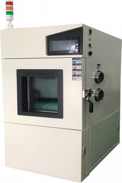
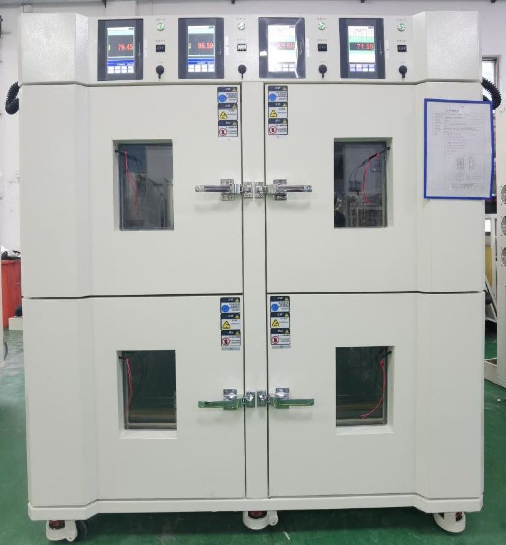
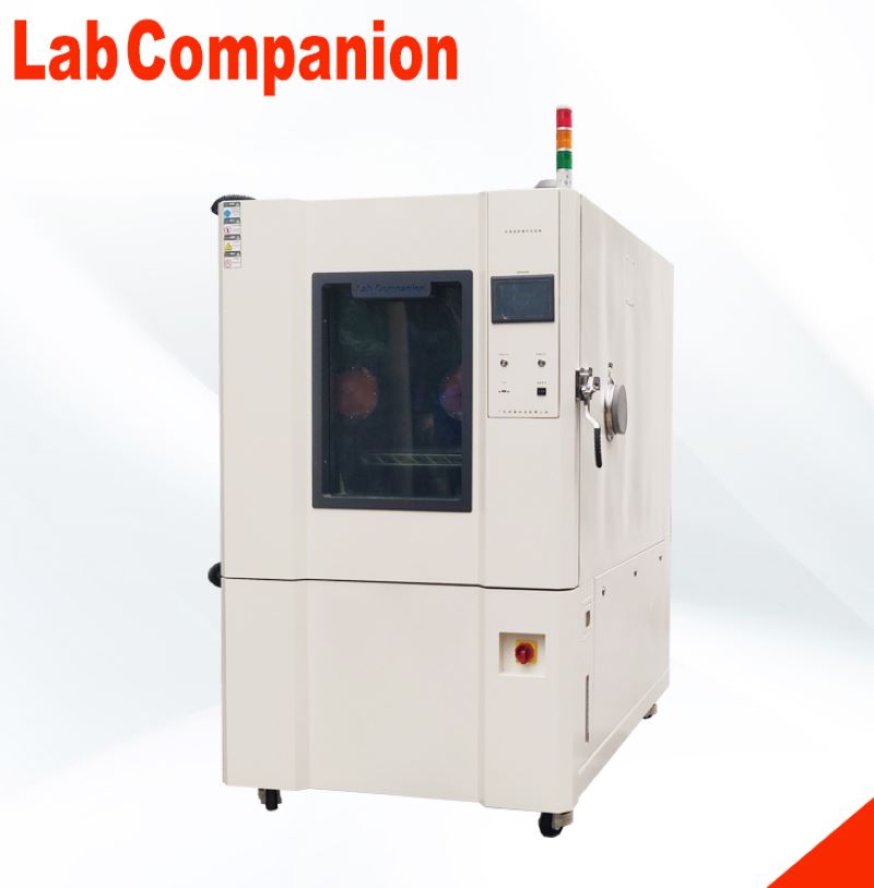
Lighting Installation Position of High and Low Temperature Test Chamber
According to the different needs of users, the installation position of the lamp in the high and low temperature laboratory is different. The constant temperature and humidity test chamber tests the heat resistance, cold resistance, dry resistance and moisture resistance of various materials. Suitable for electronic, electrical, food, vehicle, metal, chemical, building materials and other industries of quality control. This series of products is suitable for aerospace products, information electronic instruments, materials, electrical, electronic products, various electronic components in high and low temperature or temperature and humidity environment, to test its various performance indicators.
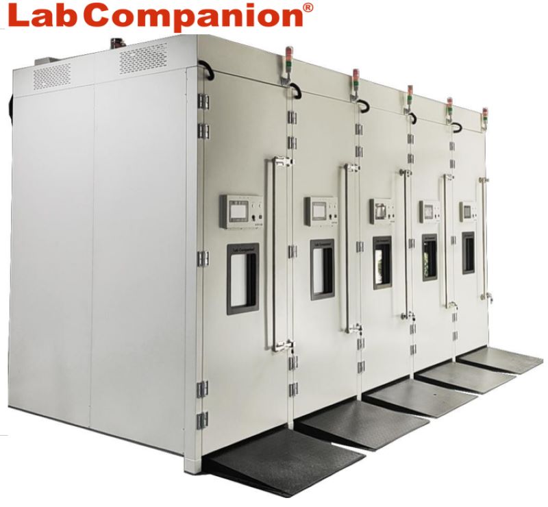
The most common temperature test equipment in environmental test equipment, and similar related products are high and low temperature alternating test chamber, constant temperature and humidity test chamber, high and low temperature and humidity alternating test chamber and so on. It is suitable for high temperature and low temperature reliability test of industrial products. Walk-in high and low temperature test chamber, walk-in high and low temperature test chamber is used for thermal test of national defense industry, aerospace industry, automatic components, automotive parts, electronic and electrical parts, plastics, chemical, pharmaceutical industry and related products. It provides large parts, semi-finished products, and large temperature and humidity test environment space for finished products. It is suitable for the test equipment with large quantity and volume.
Some are installed on the interal chamber or door, and some are not installed. Where is the best place to install light bulbs?
In fact, the high and low temperature test chamber lighting has advantages and disadvantages no matter where it is installed.
If the lighting is installed in the broadcast room, you can clearly see the condition of the entire broadcast room and observe the product at any time.
The lamp is installed on the door, and when the user conducts the double 85 test or the high temperature and high humidity test, the humidity is not easy to invade the lamp, and the lamp is not easy to damage, which can greatly reduce the after-sales service fee. However, its observation field is very small, can only observe the near attractions, customers observe the product is not very convenient.
If the lamp is installed on the right side of the internal chamber, it is recommended to be completely sealed to prevent moisture intrusion to ensure the long-term stable operation of the lamp. If it is installed on a door, it is recommended that the viewing window be trapezoid, so that you can have a wider field of view.
Of course, some corporate customers choose not to install lighting when purchasing high and low temperature test chambers to reduce production costs and later management costs. However, customers can not observe products at any time when doing tests, and they can not meet the needs of different customers who want to observe products.
Thermal Vacuum Test Chamber - Space Environment Ground Simulation Test Equipment
Product use of space environment ground simulation test equipment:
Space environment ground simulation test equipment is used for military and aerospace products in the ground environment to simulate space vacuum, cold black and solar radiation environment, thermal vacuum test and heat balance test. Space environment ground simulation test equipment can simulate the cold and hot environment of vacuum space, carry out thermal vacuum test on test pieces, and effectively control, monitor and record the temperature of test pieces in vacuum space, which provides conditions for the test of related aerospace products.
Space environment ground simulation test equipment meets the criteria:
GJB 1027A vehicle, upper stage and spacecraft test requirements
GJB 1033 satellite thermal balance test method
QJ 1446A satellite thermal balance test method
QJ2630.1 Space Environment test method for satellite components - Thermal vacuum test
QJ2630.2 Space Environment test method for satellite components - Thermal balance test
QJ2630.3 Space environment test method for satellite components - Vacuum discharge test
GB 150-1998 Steel pressure vessel
GB/T 3164-2007 Graphical symbols for system drawings of vacuum technology
GB/T 6070-2007 vacuum flange
GB 50054-1995 Design specification for low-voltage distribution
GB 50316-2008 Specification for design of industrial metal pipes
Technical parameters of space environment ground simulation test equipment:
Vacuum tank size (m) : Phi 1X1.5 Phi 2x2.5 in 3x3.5
Ultimate vacuum (pa) : ≤5x10⁻⁵
Working vacuum (pa) : ≤1.0x10⁻³
Refrigeration mode: refrigerant mode, compound working medium mode, and liquid nitrogen refrigeration mode
Heat sink + cold plate: Heat sink + heating cage Liquid nitrogen heat sink + heating cage
Temperature range: -70℃ ~ +130℃ -150℃ ~ +150℃ -173℃ ~ +170℃
Temperature stability: ≤1℃/h ≤1℃/h ≤1℃/h
Temperature uniformity: ≤±2.0℃ ≤±3.0℃ ≤±5.0℃
Temperature control accuracy: ±1℃ ±1℃ ±1℃
Rising and cooling rate: >1℃/min
Vacuum system leakage rate: <5x10⁻⁹Pam/s
Noise: Vacuum pumping equipment noise <70dB(A)
Evacuation time: The vessel can be evacuated to better than 1.0x10⁻³Pa within 4 hours at room temperature with no load.
Temperature detection system: The system adopts multi-channel Pt100 temperature inspection table to measure the temperature of named points
Control and monitoring system: Mainly includes industrial control computer, control cabinet, PLC, instrument, various operation control switches and so on
Environmental test Solutions for Vehicle Transport Auto Parts
The reliability of vehicle transportation auto parts products is very important, which directly determines the safety, reliability and operation comfort of the vehicle.
Industry
Test object
Use
Technology
Solution
Automobile industry
Automotive electronics
Inspect
High and low temperature test
High and low temperature (&humidity) test chamber
Evaluate
High and low temperature test
High temperature test chamber
Condensation power test
Rapid temperature (&humidity)change test chamber
Characteristic test
Rapid temperature (&humidity)change test chamber
Car battery
Inspect
Charge and discharge test
High and low temperature (&humidity) test chamber
Evaluate
Characteristic test
Rapid temperature (&humidity)change test chamber
Walking safety device
Inspect
Aging of the substrate
High and low temperature (&humidity) test chamber
Evaluate
Characteristic test
High temperature test chamber
Occupant protection (air bag)
Inspect
Finished product screening
Rapid temperature (&humidity)change test chamber
Car driving guidance system
Inspect
Finished product screening
High and low temperature (&humidity) test chamber
Rapid temperature (&humidity)change test chamber
ETC vehicle operation system
Inspect
High and low temperature test
High and low temperature (&humidity) test chamber
High temperature test chamber
Evaluate
Characteristic test
Rapid temperature (&humidity)change test chamber
Other automotive associations (power semiconductors)
Place at high temperature
High temperature test chamber
Battery Special Test Chamber
Introduction to the test chamber of battery special test chamber:
High and low temperature (& humidity) environment test for lithium battery cells, modules and electric vehicle power battery pack test; It is also used for high and low temperature (wet and hot) environmental tests of lithium battery cells and modules related to energy storage industry.
Main parameters of battery special test chamber:
Studio size: 0.3m ~ 1.5m³(other sizes can be customized)
Temperature range: -40 ℃ ~ +150℃
Humidity range: 20% ~ 98%
Heating rate: 1℃ -5 ℃/min (The whole process)
Cooling rate: 1℃ -5 ℃/min (The whole process)
Temperature fluctuation: ±0.5
Temperature uniformity: 2℃
Temperature deviation: ±2℃
Humidity deviation: +2 ~ -3% (> 75%RH), ± 5% (≤ 75%RH)
Burn-in Testing
Burn-in testing is the process by which a system detects early failures in semiconductor components (infant mortality), thereby increasing a semiconductor component reliability. Normally burn-in tests are performed on electronic devices such as laser diodes with an Automatic Test Equipment laser diode burn-in system that runs the component for an extended period of time to detect problems.
A burn-in system will use cutting-edge technology to test the component and provide precision temperature control, power and optical (if required) measurements to ensure the precision and reliability required for manufacturing, engineering evaluation, and R&D applications.
Burn-in testing may be conducted to ensure that a device or system functions properly before it leaves the manufacturing plant or to confirm new semiconductors from the R&D lab are meeting designed operating requirements.
It is best to burn-in at the component level when the cost of testing and replacing parts is lowest. Burn-in of a board or an assembly is difficult because different components have different limits.
It is important to note that burn-in test is usually used to filter out devices that fail during the “infant mortality stage” (beginning of bathtub curve) and does not take into count the “lifetime” or wearout (end of the bath tub curve) – this is where reliability testing comes into play.
Wearout is the natural end-of-life of a component or system related to continuous use as a result of materials interaction with the environment. This regime of failure is of particular concern in denoting the lifetime of the product. It is possible to describe wearout mathematically allowing the concept of reliability and, hence, lifetime prediction.
What Causes Components to Fail During Burn-in?
The root cause of fails detected during burn-in testing can be identified as dielectric failures, conductor failures, metallization failures, electromigration, etc. These faults are dormant and randomly manifest into device failures during device life-cycle. With burn-in testing, an Automatic Test Equipment (ATE) will stress the device, accelerating these dormant faults to manifest as failures and screen out failures during the infant mortality stage.
Burn-in testing detects faults that are generally due to imperfections in manufacturing and packaging processes, which are becoming more common with the increasing circuit complexity and aggressive technology scaling.
Burn-in Testing Parameters
A burn-in test specification varies depending on the device and testing standard (military or telecom standards). It usually requires the electrical and thermal testing of a product, using an expected operating electrical cycle (extreme of operating condition), typically over a time period of 48-168 hours. The thermal temperature of the burn-in test chamber can range from 25°C to 140°C .
Burn-in is applied to products as they are made, to detect early failures caused by faults in manufacturing practice.
Burn In Fundamentally performs the following:
Stress + Extreme Conditions + Prolong Time = Acceleration of “Normal/Useful life”
Types of Burn-in Tests
Dynamic Burn-in : the device is exposed to high voltage and temperature extremes while being subjected to various input stimuli .
A burn-in system applies various electrical stimuli to each device while the device is exposed to extreme temperature and voltage. The advantage of dynamic burn-in is its ability to stress more internal circuits, causing additional failure mechanisms to occur. However, dynamic burn-in is limited because it cannot completely simulate what the device would experience during actual use, so all the circuit nodes may not get stressed.
Static Burn-in : Device under test (DUT) is stressed at elevated constant temperature for an extended period of time.
A burn-in system applies extreme voltage or currents and temperatures to each device without operating or exercising the device. The advantages of static burn-in are its low cost and simplicity.
How is a Burn-In Test Performed?
The semiconductor device is placed onto special Burn-in Boards (BiB) while the test is executed inside special Burn-in Chamber (BIC).
Know more about Burn-in Chamber(Click here)
High and Low Temperature Low Pressure Test Equipment & Rapid Decompression Device
High and low temperature low pressure test chamber:
(1). Main technical indicators
1. Studio size: 1000D×1000W×1000H mm, the internal size is about 1000L
2. External size: about 3400D×1400W×2010H mm, excluding the controller, test hole and other prominent parts.
3. Temperature range: -70℃ ~ +150℃
4. Temperature fluctuation: ≤±0.5℃, normal pressure, no load
5. Temperature deviation: ±2℃, normal pressure, no load
6. Temperature uniformity: ≤2℃, atmospheric pressure, no-load
7. Heating rate: +20℃→+150℃≤60min
8. Cooling rate: +20℃→-65℃≤60min
9. Humidity range: Humidity 20% ~ 98%RH (temperature +20℃ ~ +85℃ range)
10. Humidity deviation: ≤+ 2-3%RH (> 75%RH), ≤±5%RH(≤75%RH), under normal pressure and no-load conditions.
11. Pressure range: normal pressure ~ 0.5kPa
12. Pressure reduction rate: normal pressure ~ 1.0kPa≤30min
13. Pressure recovery rate: ≤10.0kPa/min
14. Pressure deviation: normal pressure ~ 40kPa:≤±2kPa, 40KPa ~ 4kPa:≤±5%kPa, below 4kPa:≤± 0.1kPa
15. Wind speed: frequency conversion adjustment
16. Power: about 50kW
17. Noise: ≤75dB (A), 1 meter away from the front of the chamber and 1.2 meters above the ground.
18. Weight: 1900Kg
(2). Rapid decompression device (optional)
In order to meet the requirements of rapid depressurization, an independent rapid depressurization chamber is processed. The rapid depressurization chamber is composed of a shell assembly, a pressure assembly, a door assembly, an interface and a moving frame. Before rapid decompression, the user needs to connect an external pipeline.
1. Studio size: 400mm deep x 500mm wide x 600mm long; The internal wall material is processed with 3.0 SUS304/2B, and 5mm square pipe is used as the pressure reinforcement.
2. External dimension: 530mm deep ×700mm wide ×880mm long, the external wall material is made of 1.2mm cold-rolled steel plate, the surface is sprayed white (consistent with the color of the chamber);
3. A pressure sensor port is reserved at the top of the container. The control sensor port is located at the rear of the container to facilitate the quick buck device to be routed.
4. For the convenience of moving fast buck device. Install four lifting casters under the frame; The moving frame is welded by ordinary steel and sprayed on the surface.
5. Rapid decompression process: In order to improve the pumping speed of rapid depressurization chamber, the test chamber is first pumped to about 1kPa, and the electric valve connecting the test chamber equipment and the fast reducing device is opened to realize the fast reducing function, and the valve is closed when it reaches 18.8kPa. The constant pressure in the fast relief chamber can be achieved by auxiliary pumping (intake valve).
(3). Product implementation standards
1. GB/T2423.1-2008 Test A: Low temperature test
2. GB/T2423.2-2008 Test B: Low temperature test
3. GB/T 2423.3-2006 test Cab: constant temperature and humidity test
4. GB/T 2423.4-2008 test Db: alternating temperature and humidity test
5. GB/T2423.21-2008 Test M: Low pressure test method
6. GB/T2423.25-2008 test Z/AM: Low temperature/low pressure comprehensive test
7. GB/T2423.26-2008 Test Z/BM: high temperature/low pressure comprehensive test
8. General requirements for GJB150.1-2009
9. GJB150.2A-2009 Low pressure (altitude) test
10. GJB150.3A-2009 high temperature test
11. GJB150.4A-2009 low temperature test
12. GJB150.6-86 temperature-height test
13. GJB150.19-86 Temperature - humidity - height test
14. DO16F rapid decompression test
15. GB/T 10586-2006 temperature and humidity test chamber technical conditions
16. GB/T 10590-2006 high temperature low pressure test chamber technical conditions
17. GB/T 10592-2008 high and low temperature test chamber technical standard
18. GB/T 5170.1-2008 General Rules for inspection methods of environmental test equipment for electrical and electronic industry
19. GB/T 5170.2-2008 Electrical and electronic products environmental test equipment test method temperature and humidity test equipment
20. GB/T 5170.5-2008 Electrical and electronic products environmental test equipment test method temperature and humidity test equipment
GB/T 5170.10-2008 Electrical and electronic products environmental test equipment test method high temperature low pressure test equipment
Burn-in Board for Reliability Testing
Semiconductor equipment that test and screen out early failures during the “infant mortality” stage are put on a board known as “Burn-in Board”. On a burn-in board, there are multiple sockets to place the semiconductor device (ie. laser diode or photodiode). The number of devices which are placed on a board can consist of low batches of 64 to over 1000 devices at the same time.
These burn-in boards are then inserted into the burn-in oven which can be controlled by an ATE (Automatic Test Equipment) that supplies the mandatory voltages towards the samples while maintaining the desired oven temperature. The electrical bias applied may either be static or dynamic.
Usually the semiconductor components (ie. Laser Diodes) are pushed beyond what they will have to go through in normal use. This ensures that the manufacturer can be confident that they have a robust laser diode or photo diode device and that the component can meet reliability and qualification standards.
Burn-in Board material options:
IS410
IS410 is a high-performance FR-4 epoxy laminate and prepreg system designed to support the printed circuit board industry’s requirements for higher levels of reliability and the trend to use lead free solder.
370HR
370HR laminates and prepregs are made using a patented high performance 180°C Tg FR-4 multifunctional epoxy resin system that is designed for multilayer Printed Wiring Board (PWB) applications where maximum thermal performance and reliability are required.
BT Epoxy
BT epoxy is widely chosen for its outstanding thermal, mechanical, and electrical properties. This laminate is suitable for lead-free PCB assembly. It is primarily used for multilayer board applications. It features excellent electro migration, insulation resistance, and high thermal resistance. It also maintains bond strength at high temperature.
Polymide
BT epoxy is widely chosen for its outstanding thermal, mechanical, and electrical properties. This laminate is suitable for lead-free PCB assembly. It is primarily used for multilayer board applications. It features excellent electro migration, insulation resistance, and high thermal resistance. It also maintains bond strength at high temperature.
Nelco 4000-13
Nelco® N4000-13 series is an enhanced epoxy resin system engineered to provide both outstanding thermal and high signal speed / low signal loss properties. N4000-13 SI® is excellent for applications that require optimum signal integrity and precise impedance control, while maintaining high reliability through CAF 2 and thermal resistance.
Burn-in Board Thickness:
0.062” – 0.125” (1.57 mm – 3.17 mm)
Burn-in Board Applications:
During the burn-in process extreme temperatures often ranging from 125°C – 250°C or even 300°C are applied so the materials used need to be extremely durable. IS410 is used for burn-in board applications up to 155°C and typically a polyimide for applications up to 250°C.
Burn-in boards can be used in environmental testing conditions such as:
HAST (Highly Accelerated Temperature and Humidity Stress)
LTOL (Low Temperature Operating Life)
HTOL (High Temperature Operating Life)
Burn-in Board Design Requirements:
One of the most important considerations is selecting the highest possible reliability and quality for the Burn in Board and the test socket. You don’t want your Burn in board or socket to fail before the device under test. Therefore, all active/passive components and connectors should comply with high-temperature requirements, and all materials and components should meet high-temperature and aging requirements.
What is Environmental Testing?
The electronic devices and industrial products we rely on every day are affected by the environment in many ways, including temperature, humidity, pressure, light, electromagnetic waves and vibration. Environmental testing analyzes and evaluates the impact of these environmental factors on the product to determine its durability and reliability.
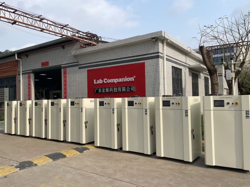
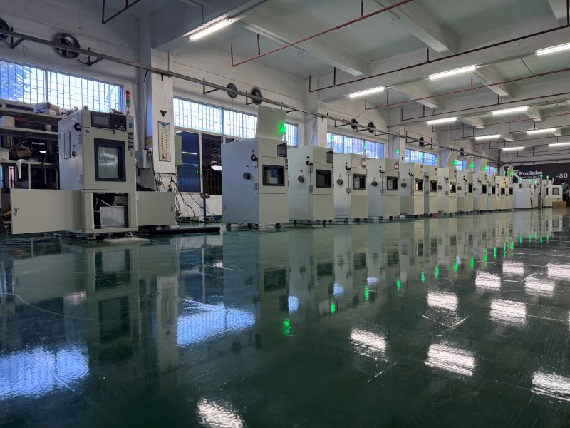
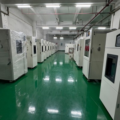
Guangdong Lab Companion LTD., has 10 million yuan registered capital and 3 R & D manufacturing plants in Dongguan, Kunshan and Chongqing. Lab Companion has been specialized in high and low temperature test equipment technology for 19 years, operating according to ISO9001, ISO14001, ISO 45001, ISO27001 four systems, setting sales and maintenance service centers in Shanghai, Wuhan, Chengdu, Chongqing, Xi 'an and Hong Kong. We work closely with International Organization of Leg al Metrology, Chinese Academy of Sciences, State Grid, China Southern Power Grid, Tsinghua University, Peking University, Hong Kong University of Science and Technology and other research institutions.
Main products of Lab Companion includes high and low temperature test chamber, constant temperature and humidity test chamber, rapid temperature cycling test chamber, thermal shock test chamber, high and low temperature and low pressure test chamber, vibration of the comprehensive chamber, industrial oven, vacuum oven, nitrogen oven, etc, providing high quality experimental equipment for universities, research institutes, medical health, inspection and quarantine, environmental monitoring, food and drugs, automobile manufacturing, petrochemical, rubber and plastic products, IC semiconductor, IT manufacturing and other fields.
Vibrational Verification for Functionality(VVF)
In the vibration generated during transportation, freight boxes are susceptible to complex dynamic pressures, and the resonant response generated is violent, which may cause packaging or product failure. Identifying the critical frequency and the type of pressure on the package will minimize this failure. Vibration testing is the assessment of the vibration resistance of components, components and complete machines in the expected transport, installation and use environment.
Common vibration modes can be divided into sinusoidal vibration and random vibration. Sinusoidal vibration is a test method often used in the laboratory, which mainly simulates the vibration generated by rotation, pulsation and oscillation, as well as the resonance frequency analysis and resonance point residence verification of the product structure. It is divided into sweep frequency vibration and fixed frequency vibration, and its severity depends on the frequency range, amplitude value and test duration. Random vibration is used to simulate the overall structural seismic strength assessment of the product and the shipping environment in the packaged state, with the severity depending on the frequency range, GRMS, test duration and axial orientation.
Vibration can not only loosen the lamp components, so that the internal relative displacement, resulting in de-welding, poor contact, poor working performance, but also make the components produce noise, wear, physical failure and even component fatigue.
To this end, Lab Companion launched a professional "LED lamp vibration test" business to simulate the vibration or mechanical shock that may occur in the actual transportation, installation and use environment of the lamp, evaluate the vibration resistance of the LED lamp and the stability of its related performance indicators, and find the weak link that may cause damage or failure. Improve the overall reliability of LED products and improve the failure status of the industry due to transportation or other mechanical shocks.
Service customers: LED lighting factory, lighting agents, lighting dealers, decoration companies
Test method:
1, the LED lamp sample packaging placed on the vibration test bench;
2, the vibration speed of the vibration tester is set to 300 RPM, the amplitude is set to 2.54 cm, start the vibration meter;
3, the lamp according to the above method in the upper and lower, left and right, front and back three directions respectively test for 30 minutes.
Results evaluation: After the vibration test, the lamp can not occur parts falling off, structural damage, lighting and other abnormal phenomena.
Double 85 Constant Temperature And Humidity Reliability Environmental Test (THB)
First, high temperature and humidity test
WHTOL (Wet High Temperature Operating Life) is a common environmental stress acceleration test, usually 85℃ and 85% relative humidity, which is generally carried out in accordance with the standard IEC 60068-2-67-2019. The test conditions are shown in the chart.
Second, the test principle
"Double 85 test" is one of the reliability environmental tests, mainly used for constant temperature and humidity box, that is, the temperature of the box is set to 85℃, the relative humidity is set to 85%RH conditions, to accelerate the aging of the test product. Although the test process is simple, the test is an important method to evaluate many characteristics of the test product, so it has become an indispensable reliability environmental test condition in various industries.
After aging the product under the condition of 85℃/85%RH, compare the performance changes of the product before and after aging, such as the photoelectric performance parameters of the lamp, the mechanical properties of the material, yellow index, etc., the smaller the difference, the better, so as to test the heat and moisture resistance of the product.
The product may have thermal failure when working in a continuous high temperature environment, and some moisture sensitive devices will fail in a high humidity environment. The dual 85 test can test the thermal stress generated by the product under high humidity and its ability to resist long-term moisture penetration. For example, the frequent failure of various products in the humid weather period in the south is mainly due to the poor temperature and humidity resistance of the products.
3. Experimental factors
In the LED lighting industry, many manufacturers have used the double 85 test results as an important means to judge the quality of lamps. Various possible reasons why LED lamps fail the dual 85 test are:
1. Lamp power supply: poor heat resistance of shell, danger of short circuit in circuit, failure of protection mechanism, etc.
2. Lamp structure: unreasonable design of heat dissipation body, installation problems, materials are not resistant to high temperature.
3. Lamp light source: poor moisture resistance, packaging adhesive aging, high temperature resistance.
If you encounter a special use environment, such as the working environment temperature is severe, you need to test its high and low temperature resistance, the test method can refer to the high and low temperature test project.
4. Serve customers
01. Customer group
LED lighting factory, LED power plant, LED packaging factory
02. Means of detection
Constant temperature and humidity test chamber
03. Reference standards
Constant temperature and humidity tests for electrical and electronic products -- Environmental testing -- Part 2: Test methods -- Test Cab: Constant temperature and humidity test GB/T 2423.3-2006.
04. Service content
4.1 Refer to the standard, conduct double 85 test on the product, and provide the third party's test results report.
4.2 Provide the analysis and improvement plan of the product through the double 85 test.
Reliability Test
AEC-Q102 Test Certification Fixed Damp Heat with Humidity Cycling (FMG), LED lamp reliability test method (GB/T 33721-2017), Component screening Ammonia test CAF test, Flame retardant grade Cyclic corrosion test (CCT), Mechanical shock test, High pressure cooker test (PCT), Highly Accelerated Stress Testing (HAST), High and low temperature and humidity test (THB), Hydrogen sulfide test (H2S), Liquid tank thermal shock test (TMSK), Component humidity sensitive grade test (MSL), Screening for high reliability use Hot flash test + acoustic sweep screening for high reliability use (MSL+SAT), LED luminaires reliability test scheme, Vibration test (VVF), Temperature cycle/thermal shock test (TC/TS), LED red Ink test UV aging test, LED light source anti-vulcanization test, Double 85 constant temperature and humidity reliability environmental test (THB), Salt spray test check.
Lab Companion-Rapid Temperature Cycling Test Chamber
Introduction of Lab Companion
With over 20 years of experience, Lab Companion is a world class manufacturer of environmental chambers and an accomplished supplier of turn-key test systems and equipment. All our chambers build on Lab Companion’s reputation for long life and exceptional reliability.
With a scope of design, manufacture and service, Lab Companion has established a quality management system that complies with the International Quality System Standard ISO 9001:2008. Lab Companion’s equipment calibration program is accredited to the International Standard ISO 17025 and the American National Standard ANSI/NCSL-Z-540-1 by A2LA. A2LA is a full member and signatory of the International Laboratory Accreditation Cooperation (ILAC), the Asia Pacific Laboratory Accreditation (APLAC) and the European Cooperation for Accreditation (EA).
Lab Companion’s SE-Series Environmental Test Chambers offer a significantly enhanced airflow system, which provides better gradients and improved product temperature change rates. These chambers utilize Thermotron’s flagship 8800 Programmer/Controller featuring a high resolution 12.1” flat panel display with touch screen user interface, expanded capabilities to graph, data log, edit, access on-screen help, and long term hard drive data storage.
Not only do we offer the highest quality products, we also provide ongoing support designed to keep you up and running long after the initial sale. We provide factory direct local service with an extensive inventory of the parts you might need.
Performance
Temperature range: -70°C to +180°C
Performance: With 23 Kg aluminum load (IEC60068-3-5), the rising rate from +85°C to -40°C is 15℃/min; the cooling rate from -40°C to +85°C is15℃/min too.
Temperature control:± 1°C Dry bulb temperatures from control point after stabilization at the control sensor
Performance is based on an ambient condition of 75°F (23.9°C) and 50% RH
Cooling/Heating Performance based on measurement at the control sensor in the supply air stream
Constructure
Interior
Nonmagnetic Series 300 stainless steel with a high nickel content
Internal seams heliarc welded for hermetic sealing of the liner
Corners and seams designed to allow for expansion and contraction under the temperature extremes encountered
Condensate drain located in the liner floor and under the conditioning plenum
Chamber base is fully welded
“Ultra-Lite” non-settling fiberglass insulation
One adjustable interior stainless steel shelf is standard
Exterior
Die-formed treated sheet steel
Metal access covers provided for easy opening doors to electrical components
Finish water-based, air dry lacquer, sprayed over a cleaned and primed surface
Easy lift-off hinged access doors for servicing the refrigeration system
One 12.5 cm diameter access port with interior weld and removable insulating plug mounted in right hand side wall accessories on hinged door for easy access
Features
Chamber Operation clearly displays helpful run-time information
Graphing Screen offers expanded capabilities, enhanced programming and reporting
System Status displays crucial refrigeration system parameters
Program Entry makes it easy to load, view and edit profiles
Set Up quick-step wizards make profile entry easy
Pop-up Refrigeration Charts for handy reference
Therm-Alarm® provides over & under temperature alarm protection
Activity Log Screen provides comprehensive equipment history
Web Server allows internet access to equipment via Ethernet
User-Friendly Pop-up Key Pad makes data entry quick and easy
Includes:
- Four USB Ports-two External & two Internal
- Ethernet
- RS-232
Technical specifications
1-4 independently programmable channels
Measuring Accuracy: 0.25% of span typical
Selectable °C or °F temperature scale
12.1” (30 cm) color flat panel touch screen display
Resolution: 0.1°C, 0.1%RH, 0.01 for other linear applications
Real time clock included
Sample Rate: Process variable sampled every 0.1 seconds
Proportional Band: Programmable 1.0° to 300°
Control Method: Digital
Intervals: Unlimited
Interval Resolution: 1 sec to 99 hrs,59 min with 1 second resolution
- RS-232
- 10+ Years Data Storage
- Product Temperature Control
- Event Relay Board
Operating Modes: Automatic or Manual
Program Storage: Unlimited
Program Loops:
- Up to 64 loops per program
Loops can be repeated up to 9,999 times program
- Up to 64 nested loops are allowed per


 Get A Quote


 IPv6 network supported