Cleaning Method of Condenser in Rapid Temperature Change Test Chamber
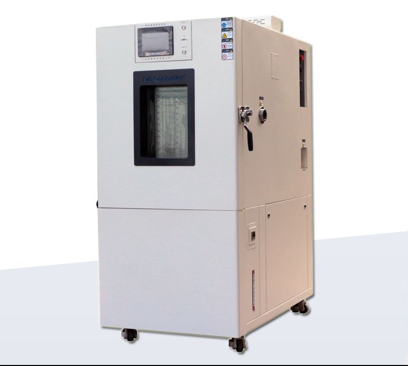
Rapid temperature change test chamber is a kind of high-precision and high-stability experimental equipment, which can carry out temperature changes in a short time to test the performance changes of materials and products at different temperatures. It is mainly used to detect the performance of products under rapid temperature changes and limit temperature conditions, and is widely used in semiconductor chips, scientific research institutions, quality inspection, new energy, optoelectronic communications, aerospace military industry, automotive industry, LCD display, medical and other science and technology industries.
After handing over the machine to the customer, in addition to instructing the precautions of equipment operation, it will also emphasize the daily maintenance of the equipment. After a long period of operation, Rapid temperature change test chamber should pay special attention to the maintenance of the refrigeration system, because the refrigeration system is not only a complex manufacturing process but also the core of the equipment refrigeration, and the next will focus on understanding the cleaning method of the condenser in the refrigeration unit.
1, Chemical pickling and scaling
For vertical and horizontal shell and tube condensers, the chemical pickling method can be used, and the weakly acidic detergent can be prepared in the pickling tank. After the pickling pump is turned on and run for 24 hours, the pickling pump is turned off, and the circular steel brush is used to brush the tube wall of the condenser back and forth, and the water is washed until all the dirt or rust stains and the scaling solution remain in the tube are clean.
2, Mechanical scaling
First, the refrigerant in the vertical shell and tube condenser is extracted, and all the valves connected to the condenser are closed, and then cooling water is normally supplied to the condenser. Use the bevel gear connected with the flexible shaft pipe washer (the diameter of the hob should be selected to be smaller than the inner diameter of the cooling pipe to scratch the inner wall) in the condenser from the top down rotary rolling mode to remove scale, because the circulating cooling water and the friction of the pipe wall generate heat, can help dirt and rust and other dirt directly washed out of the pool. After the end of descaling, drain the water in the condensate pool, clean up the dirt, and refill the water.
3, Electronic magnetic water scaling
At normal temperature, the electron magnetic water can dissolve calcium, magnesium and other salts in the cooling water of the condenser as positive and negative ions in the water. Electron magnetic water can change its crystallization conditions, can loosen the structure, reduce the tensile and compressive capacity, so that it can not form a hard scale with strong bonding force, and is converted into loose mud with the flow of cooling water and discharged.
The above is the scientific method of cleaning the condenser dirt of rapid temperature change test chamber.
What are the Types of PCB Environmental Tests?
High acceleration test:
Accelerated tests include high accelerated life test (HALT) and High accelerated Stress screening (HASS). These tests assess the reliability of products in controlled environments, including high temperature, high humidity, and vibration/shock tests when the equipment is powered on. The goal is to simulate the conditions that could lead to the imminent failure of a new product. During testing, the product is monitored in a simulated environment. Environmental testing of electronic products usually involves testing in a small environmental chamber.
Humidity and corrosion:
Many PCBS will be deployed in wet environments, so a common test for PCB reliability is a water absorption test. In this type of test, the PCB is weighed before and after being placed in a humidity controlled environmental chamber. Any water adsorbent on the board will increase the weight of the board, and any significant change in weight will result in disqualification.
When performing these tests during operation, exposed conductors should not be corroded in a humid environment. Copper oxidizes easily when it reaches a certain potential, which is why exposed copper is often plated with an antioxidant alloy. Some examples include ENIG, ENIPIG, HASL, nickel gold, and nickel.
Thermal shock and circulation:
Heat testing is usually performed separately from humidity testing. These tests include repeatedly changing the board temperature and checking how thermal expansion/contraction affects reliability. In thermal shock testing, the circuit board uses a two-chamber system to quickly move between two temperature extremes. The low temperature is usually below the freezing point, and the high temperature is usually higher than the glass transition temperature of the substrate (above ~130 ° C). The thermal cycle is carried out using a single chamber, with the temperature changing from one extreme to the other at a rate of 10°C per minute.
In both tests, the board expands or contracts as the board temperature changes. During the expansion process, conductors and solder joints are subjected to high stress, which speeds up the service life of the product and enables the identification of mechanical failure points.
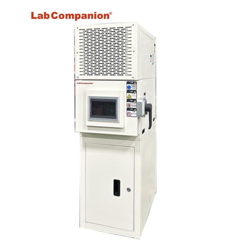
ESS Rapid Temperature Change Stress Screening Machine
Environmental Stress Screening (ESS)
Stress screening is the use of acceleration techniques and environmental stress under the design strength limit, such as: burn in, temperature cycling, random vibration, power cycle... By accelerating the stress, the potential defects in the product emerge [potential parts material defects, design defects, process defects, process defects], and eliminate electronic or mechanical residual stress, as well as eliminate stray capacitors between multi-layer circuit boards, the early death stage of the product in the bath curve is removed and repaired in advance, so that the product through moderate screening, Save the normal period and decline period of the bathtub curve to avoid the product in the process of use, the test of environmental stress sometimes lead to failure, resulting in unnecessary losses. Although the use of ESS stress screening will increase the cost and time, for improving the product delivery yield and reduce the number of repairs, there is a significant effect, but for the total cost will be reduced. In addition, customer trust will also be improved, generally for electronic parts of the stress screening methods are pre-burning, temperature cycle, high temperature, low temperature, PCB printed circuit board stress screening method is temperature cycle, for the electronic cost of the stress screening is: Power pre-burning, temperature cycling, random vibration, in addition to the stress screen itself is a process stage, rather than a test, screening is 100% of the product procedure.
Product features of rapid temperature change stress screening machine:
1, It can set different stress screening temperature variation of 5°C/min, 10°C/min and 15°C/min.
2, It can perform rapid temperature change (stress screening), condensation test, high temperature and humidity, temperature and humidity cycle and other tests.
3, It meets the requirements of electronic equipment product stress screening test.
4, It can be switched between equal temperature and average temperature two test methods.
Specification requirements of rapid temperature change stress screening machine:
1, It can set a variety of stress screening (fast temperature variability) 5°C/min, 10°C/min and 15°C/min test conditions.
2, It meets the stress screening of electronic equipment products, lead free process, MIL-STD-2164, MIL-344A-4-16, MIL-2164A-19, NABMAT-9492, GJB-1032-90, GJB/Z34-5.1.6, IPC-9701 and other test requirement.
3, It can perform equal temperature and average temperature test mode.
4, It uses aluminum sheet to verify the load capacity of the machine (non-plastic load).
New Energy Environment Test Solution
The problem of new energy reliability is still difficult, and the integrated detection system of electrical stress and environmental stress will provide the best means for research and development and manufacturing.
Industry
Test object
Use
Technology
Solution
New Energy
Battery (secondary battery)
Inspect
Charge and discharge test
High and low temperature (&humidity) test chamber
Rapid temperature (&humidity)change test chamber
Evaluate
Characteristic test
Rapid temperature (&humidity)change test chamber
Fuel cell
/
Temperature resistance
Small ultra-low temperature test chamber
High and low temperature (&humidity) test chamber
Rapid temperature (&humidity)change test chamber
Information Communication Environment Test Solution
The statistical analysis shows that the failure of electronic components accounts for 50% of the failure of electronic complete machine, and the reliability detection technology still faces many challenges.
Industry
Test object
Use
Technology
Solution
IT Communication
Transmission switching equipment
Inspect
High temperature placement test
High and low temperature (&humidity) test chamber
Aging test
High and low temperature (&humidity) test chamber
Evaluate
Thermal cycling test
High and low temperature (&humidity) test chamber
Tellcordia test
High and low temperature (&humidity) test chamber
Thermal cycling test
Rapid temperature (&humidity)change test chamber
Mobile communication terminal
Inspect
Finished operation test
High and low temperature (&humidity) test chamber
Finished operation test
Rapid temperature (&humidity)change test chamber
Evaluate
Temperature and humidity test
High and low temperature (&humidity) test chamber
Computer
Inspect
Finished product screening
Rapid temperature (&humidity)change test chamber
High temperature placement test
High and low temperature (&humidity) test chamber
Aging test
High and low temperature (&humidity) test chamber
External computer storage device
Inspect
Component screening
High and low temperature (&humidity) test chamber
Component screening
Rapid temperature (&humidity)change test chamber
Evaluate
Ensure operation test within temperature and humidity range
High and low temperature (&humidity) test chamber
Ensure operation test within temperature and humidity range
Rapid temperature (&humidity)change test chamber
Environmental Test Solutions for Electronic Products
The statistical analysis shows that the failure of electronic components accounts for 50% of the failure of electronic complete machine, and the reliability detection technology still faces many challenges.
Industry
Test object
Use
Technology
Solution
Electronic products
Semiconductor
Evaluate
Evaluation of adhesion between equipment and substrate
Rapid temperature (&humidity)change test chamber
Printed circuit board
Manufacture
Hardening and drying of insulating coatings
High temperature test chamber
Accelerated thermal cycling test
Rapid temperature (&humidity)change test chamber
Low temperature placement test
Rapid temperature (&humidity)change test chamber
LED
Evaluate
High temperature test
High temperature test chamber
Temperature cycling test
High and low temperature (&humidity) test chamber
Temperature cycling test
Rapid temperature (&humidity)change test chamber
Magnetic material
Manufacture
Drying
High temperature test chamber
/
High and low temperature (&humidity) test chamber
Battery
Evaluate
Characteristic test
Rapid temperature (&humidity)change test chamber
Environmental Test Solutions For Mechanical And Electrical Products
The statistical analysis shows that the failure of electronic components accounts for 50% of the failure of electronic complete machine, and the reliability detection technology still faces many challenges.
Industry
Test object
Use
Technology
Solution
Electromechanical
System component
Evaluate
Thermal cycling test
High and low temperature (&humidity) test chamber
Thermal cycling test
Rapid temperature (&humidity)change test chamber
Electric gas
Evaluate
Thermal cycling test
High and low temperature (&humidity) test chamber
Thermal cycling test
Rapid temperature (&humidity)change test chamber
Railway traffic
Evaluate
Thermal cycling test
High and low temperature (&humidity) test chamber
Thermal cycling test
Rapid temperature (&humidity)change test chamber
/
High and low temperature (&humidity) test chamber
/
Small ultra-low temperature test chamber
Environmental test Solutions for Vehicle Transport Auto Parts
The reliability of vehicle transportation auto parts products is very important, which directly determines the safety, reliability and operation comfort of the vehicle.
Industry
Test object
Use
Technology
Solution
Automobile industry
Automotive electronics
Inspect
High and low temperature test
High and low temperature (&humidity) test chamber
Evaluate
High and low temperature test
High temperature test chamber
Condensation power test
Rapid temperature (&humidity)change test chamber
Characteristic test
Rapid temperature (&humidity)change test chamber
Car battery
Inspect
Charge and discharge test
High and low temperature (&humidity) test chamber
Evaluate
Characteristic test
Rapid temperature (&humidity)change test chamber
Walking safety device
Inspect
Aging of the substrate
High and low temperature (&humidity) test chamber
Evaluate
Characteristic test
High temperature test chamber
Occupant protection (air bag)
Inspect
Finished product screening
Rapid temperature (&humidity)change test chamber
Car driving guidance system
Inspect
Finished product screening
High and low temperature (&humidity) test chamber
Rapid temperature (&humidity)change test chamber
ETC vehicle operation system
Inspect
High and low temperature test
High and low temperature (&humidity) test chamber
High temperature test chamber
Evaluate
Characteristic test
Rapid temperature (&humidity)change test chamber
Other automotive associations (power semiconductors)
Place at high temperature
High temperature test chamber
What is Environmental Testing?
The electronic devices and industrial products we rely on every day are affected by the environment in many ways, including temperature, humidity, pressure, light, electromagnetic waves and vibration. Environmental testing analyzes and evaluates the impact of these environmental factors on the product to determine its durability and reliability.
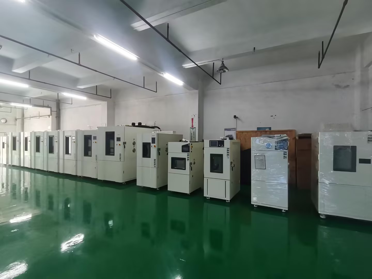
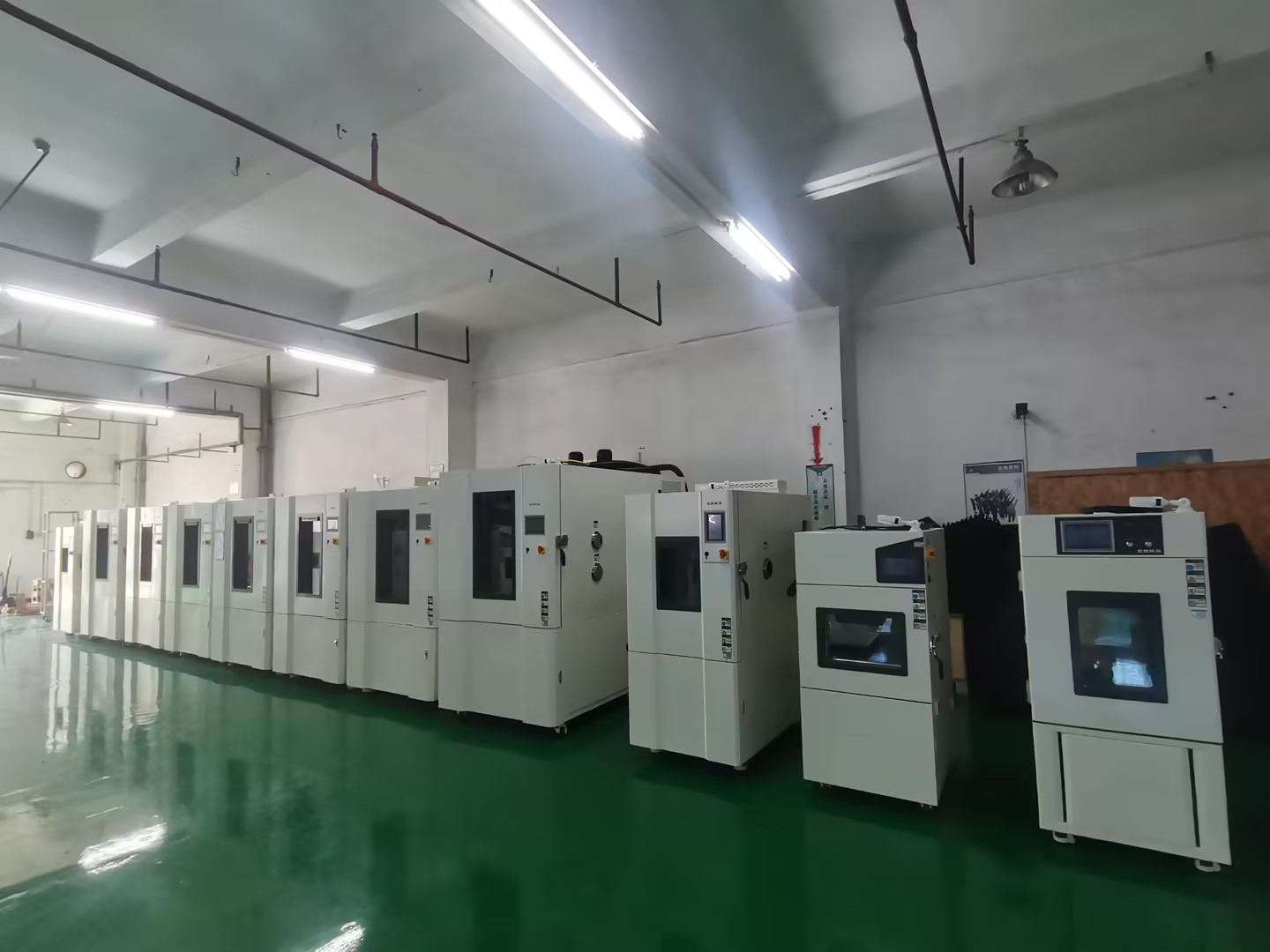
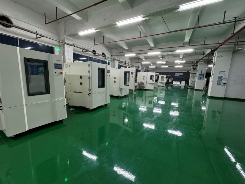
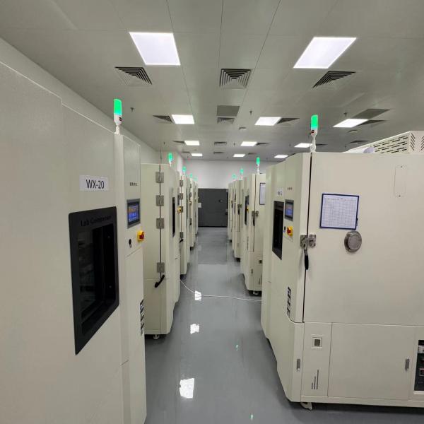
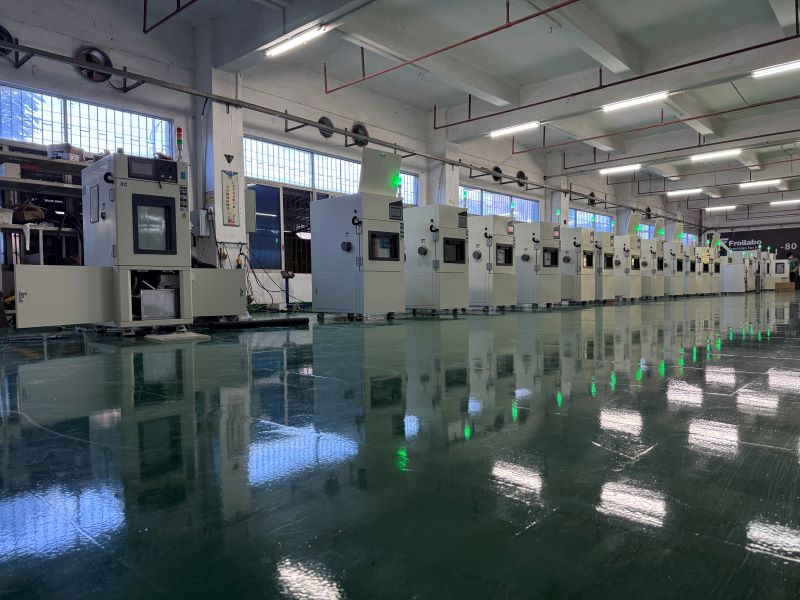
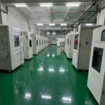
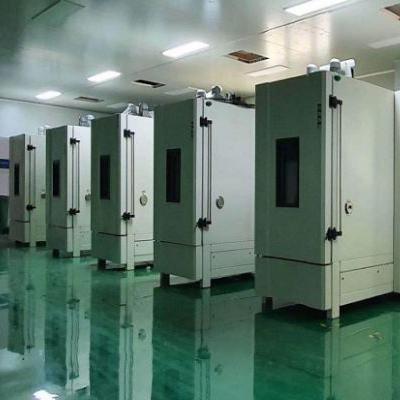
Guangdong Lab Companion LTD., has 10 million yuan registered capital and 3 R & D manufacturing plants in Dongguan, Kunshan and Chongqing. Lab Companion has been specialized in high and low temperature test equipment technology for 19 years, operating according to ISO9001, ISO14001, ISO 45001, ISO27001 four systems, setting sales and maintenance service centers in Shanghai, Wuhan, Chengdu, Chongqing, Xi 'an and Hong Kong. We work closely with International Organization of Leg al Metrology, Chinese Academy of Sciences, State Grid, China Southern Power Grid, Tsinghua University, Peking University, Hong Kong University of Science and Technology and other research institutions.
Main products of Lab Companion includes high and low temperature test chamber, constant temperature and humidity test chamber, rapid temperature cycling test chamber, thermal shock test chamber, high and low temperature and low pressure test chamber, vibration of the comprehensive chamber, industrial oven, vacuum oven, nitrogen oven, etc, providing high quality experimental equipment for universities, research institutes, medical health, inspection and quarantine, environmental monitoring, food and drugs, automobile manufacturing, petrochemical, rubber and plastic products, IC semiconductor, IT manufacturing and other fields.
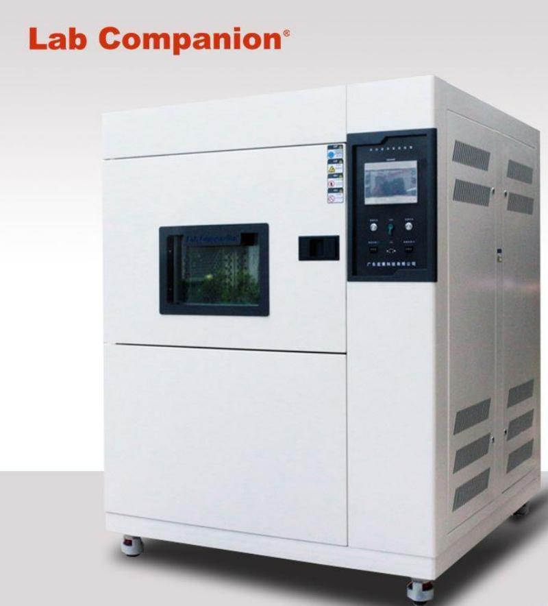
Thermal Cycling Test(TC) & Thermal Shock Test(TS)
Thermal Cycling Test(TC):
In the life cycle of the product, it may face various environmental conditions, which makes the product appear in the vulnerable part, resulting in product damage or failure, and then affect the reliability of the product.
A series of high and low temperature cycling tests are done on the temperature change at the temperature variation rate of 5~15 degrees per minute, which is not a real simulation of the actual situation. Its purpose is to apply stress to the test piece, accelerate the aging factor of the test piece, so that the test piece may cause damage to the system equipment and components under environmental factors, in order to determine whether the test piece is correctly designed or manufactured.
Common ones are:
Electrical function of the product
The lubricant deteriorates and loses lubrication
Loss of mechanical strength, resulting in cracks and cracks
The deterioration of the material causes chemical action
Scope of application:
Module/system product environment simulation test
Module/System Product Strife test
PCB/PCBA/ Solder Joint Accelerated Stress Test (ALT/AST)...
Thermal Shock Test(TS):
In the life cycle of the product, it may face various environmental conditions, which makes the product appear in the vulnerable part, resulting in product damage or failure, and then affect the reliability of the product.
High and low temperature shock tests under extremely harsh conditions on rapid temperature changes at a temperature variability of 40 degrees per minute are not truly simulated. Its purpose is to apply severe stress to the test piece to accelerate the aging factor of the test piece, so that the test piece may cause potential damage to the system equipment and components under environmental factors, in order to determine whether the test piece is correctly designed or manufactured.
Common ones are:
Electrical function of the product
The product structure is damaged or the strength is reduced
Tin cracking of components
The deterioration of the material causes chemical action
Seal damage
Machine specifications:
Temperature range: -60 ° C to +150 ° C
Recovery time: < 5 minutes
Inside dimension: 370*350*330mm (D×W×H)
Scope of application:
PCB reliability acceleration test
Accelerated life test of vehicle electric module
LED parts accelerated test...
Effects of temperature changes on products:
The coating layer of components falls off, the potting materials and sealing compounds crack, even the sealing shell cracks, and the filling materials leak, which causes the electrical performance of components to decline.
Products composed of different materials, when the temperature changes, the product is not evenly heated, resulting in product deformation, sealing products cracking, glass or glassware and optics broken;
The large temperature difference makes the surface of the product condense or frost at low temperature, evaporates or melts at high temperature, and the result of such repeated action leads to and accelerates the corrosion of the product.
Environmental effects of temperature change:
Broken glass and optical equipment.
The movable part is stuck or loose.
Structure creates separation.
Electrical changes.
Electrical or mechanical failure due to rapid condensation or freezing.
Fracture in a granular or striated manner.
Different shrinkage or expansion characteristics of different materials.
The component is deformed or broken.
Cracks in surface coatings.
Air leak in the containment compartment.
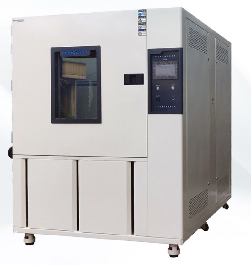
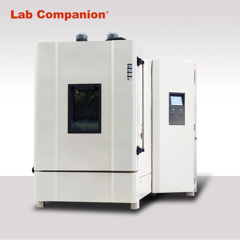
Lab Companion-Rapid Temperature Cycling Test Chamber
Introduction of Lab Companion
With over 20 years of experience, Lab Companion is a world class manufacturer of environmental chambers and an accomplished supplier of turn-key test systems and equipment. All our chambers build on Lab Companion’s reputation for long life and exceptional reliability.
With a scope of design, manufacture and service, Lab Companion has established a quality management system that complies with the International Quality System Standard ISO 9001:2008. Lab Companion’s equipment calibration program is accredited to the International Standard ISO 17025 and the American National Standard ANSI/NCSL-Z-540-1 by A2LA. A2LA is a full member and signatory of the International Laboratory Accreditation Cooperation (ILAC), the Asia Pacific Laboratory Accreditation (APLAC) and the European Cooperation for Accreditation (EA).
Lab Companion’s SE-Series Environmental Test Chambers offer a significantly enhanced airflow system, which provides better gradients and improved product temperature change rates. These chambers utilize Thermotron’s flagship 8800 Programmer/Controller featuring a high resolution 12.1” flat panel display with touch screen user interface, expanded capabilities to graph, data log, edit, access on-screen help, and long term hard drive data storage.
Not only do we offer the highest quality products, we also provide ongoing support designed to keep you up and running long after the initial sale. We provide factory direct local service with an extensive inventory of the parts you might need.
Performance
Temperature range: -70°C to +180°C
Performance: With 23 Kg aluminum load (IEC60068-3-5), the rising rate from +85°C to -40°C is 15℃/min; the cooling rate from -40°C to +85°C is15℃/min too.
Temperature control:± 1°C Dry bulb temperatures from control point after stabilization at the control sensor
Performance is based on an ambient condition of 75°F (23.9°C) and 50% RH
Cooling/Heating Performance based on measurement at the control sensor in the supply air stream
Constructure
Interior
Nonmagnetic Series 300 stainless steel with a high nickel content
Internal seams heliarc welded for hermetic sealing of the liner
Corners and seams designed to allow for expansion and contraction under the temperature extremes encountered
Condensate drain located in the liner floor and under the conditioning plenum
Chamber base is fully welded
“Ultra-Lite” non-settling fiberglass insulation
One adjustable interior stainless steel shelf is standard
Exterior
Die-formed treated sheet steel
Metal access covers provided for easy opening doors to electrical components
Finish water-based, air dry lacquer, sprayed over a cleaned and primed surface
Easy lift-off hinged access doors for servicing the refrigeration system
One 12.5 cm diameter access port with interior weld and removable insulating plug mounted in right hand side wall accessories on hinged door for easy access
Features
Chamber Operation clearly displays helpful run-time information
Graphing Screen offers expanded capabilities, enhanced programming and reporting
System Status displays crucial refrigeration system parameters
Program Entry makes it easy to load, view and edit profiles
Set Up quick-step wizards make profile entry easy
Pop-up Refrigeration Charts for handy reference
Therm-Alarm® provides over & under temperature alarm protection
Activity Log Screen provides comprehensive equipment history
Web Server allows internet access to equipment via Ethernet
User-Friendly Pop-up Key Pad makes data entry quick and easy
Includes:
- Four USB Ports-two External & two Internal
- Ethernet
- RS-232
Technical specifications
1-4 independently programmable channels
Measuring Accuracy: 0.25% of span typical
Selectable °C or °F temperature scale
12.1” (30 cm) color flat panel touch screen display
Resolution: 0.1°C, 0.1%RH, 0.01 for other linear applications
Real time clock included
Sample Rate: Process variable sampled every 0.1 seconds
Proportional Band: Programmable 1.0° to 300°
Control Method: Digital
Intervals: Unlimited
Interval Resolution: 1 sec to 99 hrs,59 min with 1 second resolution
- RS-232
- 10+ Years Data Storage
- Product Temperature Control
- Event Relay Board
Operating Modes: Automatic or Manual
Program Storage: Unlimited
Program Loops:
- Up to 64 loops per program
Loops can be repeated up to 9,999 times program
- Up to 64 nested loops are allowed per
Smart Watch Reliability Test Conditions
In today's society, elementary school students and even kindergarten children have a smart watch. So, what is a smartwatch? In the late period of sports watch promotion due to the rapid takeoff of smart phones, the smart table has no intention to provide the same PIM effect as PDA and smart phones, and appeals to the smart phone agent assistant accessories, similar to Bluetooth headphones are voice AIDS of smart phones, smart tables become information and data AIDS, providing more convenient and fast information display and operation. There are also other names such as Smart Accessory and Android Remote. Positioned as a mobile phone assistant, the idea is that "the reason why the pocket watch is extinct is because it is simply to look at the time, but also take out the pocket, about 2-3 seconds, but the watch is less than 1 second, which is more convenient than the pocket watch." And after observation, now everyone takes out a smartphone and slides open, just to confirm the message, so that about dozens of times, these confirmation even typing reply do not need, if the dozens of confirmation changed on the watch, you do not always have to pull the machine slide unlock, because this is as time-consuming as a pocket watch. Therefore, after becoming the assistant of the mobile phone, the remote control, if you do not take the mobile phone to go out, the watch is useless in addition to showing the time, and the Bluetooth headset without a mobile phone, almost scrap metal.
Combined with smart bracelet to sell better!!
Smart watch from "smaller than the PDA independent computer" to "smart phone remote control AIDS", seems to have been a more successful positioning, but this CES 2014 can be seen, combined with smart bracelet positioning is better. The smart wristband uses acceleration sensors (and gyroscopes, magnetoresistive sensors, etc.) to sense the user's running speed, step count, etc., and can even detect deep sleep and provide suggestions for exercise and sleep. When the wristband is added to the display, it can display the time and information on the mobile phone. Appeal to mobile phone information, if there is no urgent information needs, in fact, only similar to the Bluetooth headset is regarded as an option (Courier, driver need), if everyone can accept the information access speed of sliding, then the market will be limited. However, in addition to the appeal for exercise and sleep record supervision, and emphasize information tips, rather than emphasizing the remote control of the watch on the mobile phone, it is equivalent to a little sacrifice or almost no sacrifice to the end user, but it brings immediate and new application value (sports, sleep assistance), rather than completely repeating the efficacy value of the mobile phone, which further increases the market success of the smart watch. After constantly adjusting the efficacy, application and positioning, and integrating with the smart ring, we believe that we can have a higher market than in the past.
Smart watch for people and functions:
1. Smart watches for adults
Functions: Bluetooth synchronous mobile phone calls, send and receive text messages, monitor sleep, monitor heart rate, sedentary reminder, running, remote photography, music playback, video, compass and other functions, designed for fashion trend people!
2, Smart watch for the elderly
Functions: ultra-accurate GPS positioning, family calls, emergency calls, heart rate monitoring, sedentary reminders, medicine reminders and other customized functions for the elderly, providing an umbrella for the elderly's travel, bring this watch, refuse to lose the elderly!
3, Children positioning smart watch
Functions: multiple positioning, two-way call, SOS SOS, remote monitoring, intelligent anti-loss, historical track, electronic fence, pedometer, love reward and other functions, to ensure the safety of children, give children a healthy and safe growth environment!
Smart watch specification:
IEC 60086-3: Watch batteries
ISO 105-A02: Colour fastness test -A02 - Grey scale assessment for discoloration
ISO 105-A03-1993: Tests for colour fastness -A03- Grey scale assessment of dyeing
ISO 764: Horological anti-magnetic watches
ISO 1413: Horological shockproof watches
ISO 2281: Horological waterproof watches
ISO 11641-1993: Leather - tests for colour fastness - Colour fastness to perspiration
ISO 14368-3: Impact resistance test of table glass
MIL 810G: Environmental engineering considerations and laboratory testing
QB/T 1897-1993: Waterproof watch inspection
QB/T 1898-1993: Inspection of shockproof watches
QB/T 1908-1993: Key reliability test
QB/T 1919-2012: Type inspection of digital quartz watches with hands and liquid crystal
QB/T 2047-2007: Inspection of metal watchbands
GB/T 2537-2001: leather color fastness test reciprocating grinding color fastness
QB/T 2540-2002: Leather strap inspection
GB/T 6048-1985: digital quartz electronic watch
GB/T 18761-2007: electronic digital display indicator
GB/T 18828-2002: Standard for diving watches
GB/T 22778-2008: LCD digital quartz stopwatch type inspection
GB/T 22780-2008: Type inspection of LCD quartz watches
GB/T 26716-2011 idt ISO 764-2002: Inspection of anti-magnetic watches
HJ216-2005: Eco-Drive watch
Smart watch pilot project:
Reliability, time period measurement accuracy, instantaneous daily difference, operating temperature, voltage range, average temperature coefficient, voltage coefficient, moisture resistance, shock resistance, waterproof performance, battery replacement cycle, key fatigue resistance, light and weather resistance, antistatic performance Ambient temperature range: -25℃ ~ 55℃ Operating temperature: -5 ~ 50℃/80%R.H.(Requirements: each function and liquid crystal display should be complete and normal) High and low working temperature test: 50±1℃/24h→RT/1h→-5±1℃ Temperature change test conditions: (IEC60068-2) High temperature: 30, 40, 55℃ Low temperature: 5, -5, -10, -25℃ Nb residence time (including rising and cooling time) : 10min, 30min, 1hr Nb temperature variability: 3±0.6℃/min, 5±1℃/min.
Wet heat test:
1.40±1℃/85 ~ 95%R.H./24h
2.8±1℃/85 ~ 95%R.H./4h
Warehouse storage humidity test:
40℃/20%, 30%, 40%, 50%, 60%, 70%, 80%, 90%
49℃/10%, 20%, 30%, 40%, 50%, 60%, 70%, 80%, 90%
Each step37 hours
Air transport temperature change simulation test:
Specification: IEC60721.2 Electrical and electronic products application environmental conditions - transport national standard
Category: 2K5 (Applicable to the climatic range of unventilated and unpressurized internal transport worldwide)
Temperature range: -65℃←→85℃
RAMP: 5℃/min
Air transport temperature change simulation test:
Specification: IEC60721.6 Electrical and electronic products application environmental conditions - Marine
Category: 6K5 (subject to cold weather, installed in weather-protected but unheated parts)
Temperature range: -25℃←→40℃
RAMP: 3℃/min
Water temperature change resistance test:
5min in 40℃ water → 5min in 20℃ water, 5min in 40℃ water, water depth of 10cm
Water pressure resistance test:
Soak the watch in a container of water, apply an overpressure of 2*10^5Pa[or 20m water depth] within 1 minute, maintain 10 minutes, and then in 1 minute the pressure will be to the standard pressure of the surrounding environment
Salt water resistance test:
Put the watch under test into 30g/L sodium chloride solution at 18 ° C ~ 25 ° C for 24h. Check the case and accessories after the test should not have significant changes; Check the moving parts, especially the rotating front ring should be able to maintain normal function
Underwater reliability test:
The watch under test is immersed in 30cm±2cm of water and placed at a temperature of 18 ° C ~ 25 ° C for 50h, and all mechanical devices should still work normally. During the test, mechanical devices that need to be operated in water, such as time presetting devices and light switches, should be able to work normally; Do condensation test, the inner surface of the table glass shall not appear condensation fog, and the mechanical function should not be damaged
Thermal shock resistance test:
Immerse the watch in water of different temperatures with a depth of 30cm±2cm successively: place it in water of 40 ° C ±2 ° C for 10 minutes; Put in 5℃±2℃ water for 10 minutes; Put in water at 40 ° C ± 2 ° C for 10 minutes (the watch shall not be removed from the water and re-immersed in another water temperature for more than 1 minute). Do condensation test, the inner surface of the table glass shall not appear condensation fog, and should operate normally.
Chemical resistance test:
Citation Specifications: ASTM F 1598-95, ASTM D 1308-87, ASTM D 1308-02
Ingredients: Household chemicals (dirt, dust, oil, fumes and peanut butter, cosmetics, hand cream... Etc.)
Time: 24 hours
Corrosion resistance to artificial sweat test:
QB/T 1901.2-2006 "Gold alloy covers of shell and its accessories - Part 2 Test for purity, thickness, corrosion resistance and adhesion"
Test principle: The artificial sweat is used to contact the object under high temperature (40±2) ℃, and after a long time (not less than 24 hours), the condition of its surface is observed to determine its resistance to sweat corrosion.
Vibration test:
Acceleration (19.6m/s^2), frequency 30Hz ~ 120Hz, scanning cycle 1min
Requirements: The functions and the LCD display should be complete and normal, and the parts should not be loose and fall off
Drop test:
1m drop lithographic hardwood, once watch side, once surface glass
Requirements: Normal function after each impact, no appearance damage [broken glass, case foot bent, case component bent, case broken, button damaged]
Impact test:
Impact cone pad material: polytetrafluoroethylene, impact speed 4.43m/s, impact height 1m
Arm swing test:
2 to 10Hz


 Get A Quote


 IPv6 network supported