Construction and System Software of Two-zone Thermal Shock Test Chamber
Construction of Two-zone Thermal Shock Test Chamber:
1, Construction mode of environmental test chamber:
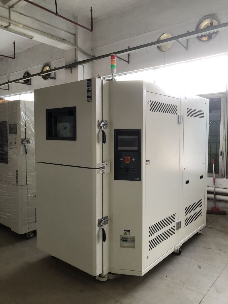
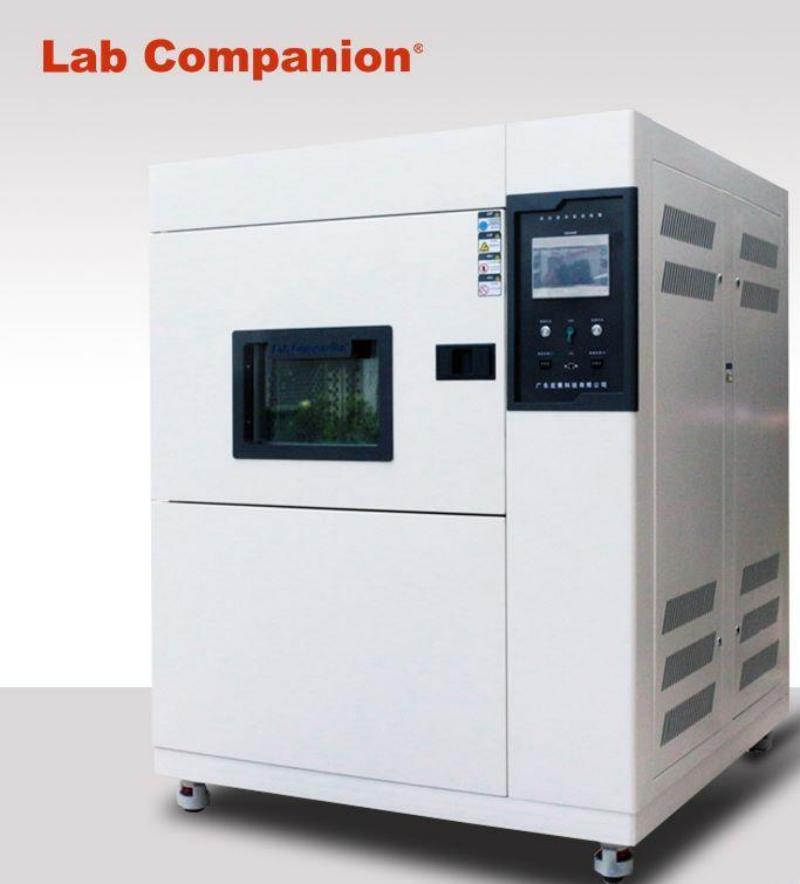
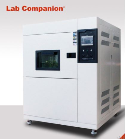
Environmental test chamber is composed of a high temperature test chamber located at the upper end, a low temperature test chamber located below, a freezer cabinet located at the back and a home appliance control chamber (system software) located on the right. In this way, the shell occupies a small area, compact structure, beautiful appearance design, the freezer unit is placed in a separate generator chamber body, in order to reduce the vibration and noise of the freezer unit operation on the environmental test chamber harm, in addition to the installation and maintenance of the generator set, the household appliance operation panel is placed on the right panel of the environmental test chamber to facilitate the operation of the actual operation;
2, Shell surface raw materials: cold-rolled plate, surface electrostatic powder spraying solution;
3, The shell cavity raw materials: imported stainless steel plate (SUS304);
4, Thermal insulation material: heat resistant hard plastic polyamine ester foam + foam glass plate;
5, The door: single door, equipped with double silicone rubber sealing and sealing rubber strip heating equipment, under the self-limiting temperature heating zone, to avoid the experiment essence and frost;
6, Test rack: move up and down left and right sliding type stainless steel plate test rack. The pneumatic double-effect cylinder shows a stable and symmetrical driving force. The positioning device of the test rack uses an electromagnetic field triggered limit switch;
7, Cable wire installation hole: the upper end of the test rack and the top of the high temperature test chamber is provided with a telescopic cable threading tube.
Air conditioning system software of two-zone thermal shock test chamber:
1, Gas control method: forced circulation system natural ventilation, balanced temperature control method (BTC). The method refers to the refrigeration unit in the continuous operation of the condition, the automatic control system according to the temperature point set according to the PID automatic and operational output results to manipulate the electric heater's heart output, the ultimate UI will exceed this stable balance.
2, Gas circulation system equipment: embedded central air conditioning room, air supply mode channel and stainless steel plate short-axis exhaust fan, the application of refrigeration unit and kinetic energy adjustment system software, according to the exhaust fan to carry out a reasonable heat exchanger, more than the purpose of maintaining temperature change. According to the improved air flow of the gas, the total gas flow and the working capacity of the heat exchanger with the electric heater and the surface cooler are improved.
3, Evaporative cooling method: fin type air heat exchanger.
4. Gas heating method: select nickel-chromium wire electric heater.
How to Change the Refrigerant Oil of Thermal Shock Test Chamber?
Thermal shock test chamber is a necessary test equipment for metal, plastic, rubber, electronics and other material industries, used to test material structure or composite materials, in an instant under the continuous environment of extremely high temperature and extremely low temperature to endure the degree of chemical changes or physical damage caused by thermal expansion and contraction of the sample in the shortest time. Thermal shock test chamberr meets the test method: GB/T2423.1.2, GB/T10592-2008, GJB150.3 thermal shock test.
In thermal shock test chamber, if the compressor is semi-closed piston compressor in operation for 500 hours, it is necessary to observe the oil temperature and oil pressure changes of the frozen oil, and if the frozen oil is discolored, it must be replaced. After the initial operation of the compressor unit for 2000 hours, the cumulative operation of three years or the operation time of more than 10,000 to 12,000 hours should be maintained within a time limit and the chilled oil should be replaced.
The refrigerated oil replacement of the semi-closed piston compressor in thermal shock test chamber can be performed according to the following steps:
1, Close high pressure exhaust and low pressure suction stop valve of thermal shock test chamber, and then screw down the oil plug, the oil plug is generally in the bottom of the crankcase, and then put the frozen oil clean and clean the filter.
2, Use the low-pressure impact gas valve needle to blow nitrogen into the oil port and then use the pressure to discharge the residual oil in the body, install a clean filter and tighten the oil plug.
3. Connect the low pressure tube filled with fluorine gauge to the low pressure process valve needle with a vacuum pump to pump the crankcase into negative pressure, and then remove the other fluorine tube separately, put one end into the chilled oil, and put the other end on the valve needle of the low pressure suction of the oil pump. The chilled oil is sucked into the crankcase due to the negative pressure, and add it to the position slightly higher than the lower limit of the oil mirror line.
4. After injection, tighten the process column or remove the fluorine filling tube, and then connect the fluorine pressure gauge to vacuum the compressor.
5. After vacuuming, it is necessary to open the high and low pressure stop valve of the compressor to check whether the refrigerant has leaked.
6, Open thermal shock test chamber unit to check the lubrication of the compressor and the oil level of the oil mirror, the oil level can not be less than a quarter of the mirror.
The above is how to replace the refrigerant oil of the semi-closed piston compressor in thermal shock test chamber. Because the refrigerant oil has hygroscope, the replacement process needs to reduce the air entering the system and the oil storage container. If the cold aging oil is injected too much, there is the risk of liquid shock.
Thermal Cycling Test(TC) & Thermal Shock Test(TS)
Thermal Cycling Test(TC):
In the life cycle of the product, it may face various environmental conditions, which makes the product appear in the vulnerable part, resulting in product damage or failure, and then affect the reliability of the product.
A series of high and low temperature cycling tests are done on the temperature change at the temperature variation rate of 5~15 degrees per minute, which is not a real simulation of the actual situation. Its purpose is to apply stress to the test piece, accelerate the aging factor of the test piece, so that the test piece may cause damage to the system equipment and components under environmental factors, in order to determine whether the test piece is correctly designed or manufactured.
Common ones are:
Electrical function of the product
The lubricant deteriorates and loses lubrication
Loss of mechanical strength, resulting in cracks and cracks
The deterioration of the material causes chemical action
Scope of application:
Module/system product environment simulation test
Module/System Product Strife test
PCB/PCBA/ Solder Joint Accelerated Stress Test (ALT/AST)...
Thermal Shock Test(TS):
In the life cycle of the product, it may face various environmental conditions, which makes the product appear in the vulnerable part, resulting in product damage or failure, and then affect the reliability of the product.
High and low temperature shock tests under extremely harsh conditions on rapid temperature changes at a temperature variability of 40 degrees per minute are not truly simulated. Its purpose is to apply severe stress to the test piece to accelerate the aging factor of the test piece, so that the test piece may cause potential damage to the system equipment and components under environmental factors, in order to determine whether the test piece is correctly designed or manufactured.
Common ones are:
Electrical function of the product
The product structure is damaged or the strength is reduced
Tin cracking of components
The deterioration of the material causes chemical action
Seal damage
Machine specifications:
Temperature range: -60 ° C to +150 ° C
Recovery time: < 5 minutes
Inside dimension: 370*350*330mm (D×W×H)
Scope of application:
PCB reliability acceleration test
Accelerated life test of vehicle electric module
LED parts accelerated test...
Effects of temperature changes on products:
The coating layer of components falls off, the potting materials and sealing compounds crack, even the sealing shell cracks, and the filling materials leak, which causes the electrical performance of components to decline.
Products composed of different materials, when the temperature changes, the product is not evenly heated, resulting in product deformation, sealing products cracking, glass or glassware and optics broken;
The large temperature difference makes the surface of the product condense or frost at low temperature, evaporates or melts at high temperature, and the result of such repeated action leads to and accelerates the corrosion of the product.
Environmental effects of temperature change:
Broken glass and optical equipment.
The movable part is stuck or loose.
Structure creates separation.
Electrical changes.
Electrical or mechanical failure due to rapid condensation or freezing.
Fracture in a granular or striated manner.
Different shrinkage or expansion characteristics of different materials.
The component is deformed or broken.
Cracks in surface coatings.
Air leak in the containment compartment.
Heat Pipe Reliability Test
Heat pipe technology is a heat transfer element called "heat pipe" invented by G.M. rover of Los Alamos National Laboratory in 1963, which makes full use of the principle of heat conduction and the rapid heat transfer properties of the refrigeration medium, and transfers the heat of the heating object quickly to the heat source through the heat pipe. Its thermal conductivity exceeds that of any known metal. Heat pipe technology has been widely used in aerospace, military and other industries, since it has been introduced into the radiator manufacturing industry, making people change the design idea of the traditional radiator, and get rid of the single heat dissipation mode that simply relies on high air volume motor to obtain better heat dissipation effect. The use of heat pipe technology makes the radiator even if the use of low speed, low air volume motor, can also get satisfactory results, so that the noise problem plagued by air cooling heat has been well solved, opening up a new world in the heat dissipation industry.
Heat pipe reliability test conditions:
High temperature stress screening test: 150℃/24 hours
Temperature cycling test:
120℃(10min)←→-30℃(10min), Ramp: 0.5℃, 10cycles 125℃(60min)←→-40℃(60min), Ramp: 2.75℃, 10cycles
Thermal shock test:
120℃(2min)←→-30℃(2min), 250 cycles
125℃(5min)←→-40℃(5min), 250 cycles
100℃(5min)←→-50℃(5min), 2000 cycles(check once after 200 cycles)
High temperature and high humidity test:
85℃/85%R.H./1000 hours
Accelerated aging test:
110℃/85%RH/264h
Other heat pipe test items:
Salt spray test, strength (blasting) test, leakage rate test, vibration test, random vibration test, mechanical shock test, helium combustion test, performance test, wind tunnel test
Reliability of Ceramic Substrate
Ceramic PCB (Ceramic Substrate) refers to a special process plate where copper foil is directly bonded to the surface (single or double) of alumina (Al2O3) or aluminum nitride (AlN) ceramic substrate at high temperature. The ultra-thin composite substrate has excellent electrical insulation performance, high thermal conductivity, excellent soldering and high adhesion strength, and can be etched into a variety of graphics like PCB board, with great current carrying capacity. Therefore, the ceramic substrate has become the basic material of high-power electronic circuit structure technology and interconnect technology, which is suitable for products with high caloric value (high-brightness LED, solar energy), and its excellent weather resistance can be applied to harsh outdoor environments.
Main application products: high power LED carrier board, LED lights, LED street lights, solar inverter
Ceramic substrate features:
Structure: Excellent mechanical strength, low warping, thermal expansion coefficient close to silicon wafer (aluminum nitride), high hardness, good processability, high dimensional accuracy
Climate: Suitable for high temperature and humidity environment, high thermal conductivity, good heat resistance, corrosion and wear resistance, UV& yellowing resistance
Chemistry: Lead-free, non-toxic, good chemical stability
Electrical: high insulation resistance, easy metallization, circuit graphics and strong adhesion
Market: Abundant materials (clay, aluminum), easy to manufacture, low price
PCB material thermal characteristics comparison (conductivity) :
Glass fiber board (traditional PCB) : 0.5W/mK, aluminum substrate: 1~2.2W/mK, ceramic substrate: 24[alumina]~170[aluminum nitride]W/mK
Material heat transfer coefficient (unit W/mK) :
Resin: 0.5, alumina: 20-40, silicon carbide: 160, aluminum: 170, aluminum nitride: 220, copper: 380, diamond: 600
Ceramic substrate process classification:
According to the line ceramic substrate process is divided into: thin film, thick film, low temperature co-fired multi-layer ceramic (LTCC)
Thin Film Process (DPC) : Precise control of component circuit design (line width and film thickness)
Thick film process (Thick film) : to provide heat dissipation and weather conditions
Low temperature co-fired multilayer ceramic (HTCC) : The use of glass ceramics with low sintering temperature, low melting point, high conductivity of precious metal co-fired characteristics, multi-layer ceramic substrate) and assembly.
Low temperature co-fired multilayer ceramics (LTCC) : Stack several ceramic substrates and embed passive components and other ics
Thin film ceramic substrate process:
· Pretreatment → sputtering → photoresistance coating → exposure development → line plating → film removal
· Lamination → hot pressing → degreasing → substrate firing → circuit pattern formation → circuit firing
· Lamination → surface printed circuit pattern → hot pressing → degreasing → co-firing
· Printed circuit graphics → lamination → hot pressing → degreasing → co-firing
Ceramic substrate reliability test conditions:
Ceramic substrate high temperature operation: 85℃
Ceramic substrate low temperature operation: -40℃
Ceramic substrate cold and thermal shock:
1. 155℃(15min)←→-55℃(15min)/300cycle
2. 85 ℃ (30 min) please - - 40 ℃ (30 min)/RAMP: 10 min (12.5 ℃ / min) / 5 cycle
Ceramic substrate adhesion: Stick to the surface of the board with 3M#600 tape. After 30 seconds, tear quickly in a 90° direction with the surface of the board.
Ceramic substrate red ink experiment: Boil for one hour, impermeable
Test equipment:
1.High and low temperature humid heat test chamber
2. Three-box gas type cold and heat shock test chamber
Tablet Reliability Test
A Tablet Computer, also known as a Tablet Personal Computer (Tablet PC), is a small, portable personal computer that uses a touch screen as its basic input device. It is an electronic product with strong mobility, and it can be seen everywhere in life (such as waiting stations, trains, high-speed trains, cafes, restaurants, meeting rooms, suburbs, etc.). People carry only simple coat protection or even no, in order to facilitate use, the design reduces the size, so that it can be directly placed in the pocket or handbag, backpack, but the tablet computer in the process of moving will also experience many environmental physical changes (such as temperature, humidity, vibration, impact, extrusion, etc.). Etc.) and natural damage (such as ultraviolet light, sunlight, dust, salt spray, water droplets... It will also cause artificial unintentional injury or abnormal operation and misoperation, and even cause failure and damage (such as: household chemicals, hand sweating, falling, terminal insertion and removal too much, pocket friction, crystal nails... These will shorten the life of the tablet computer, in order to ensure the reliability of the product and extend the service life to improve, we must carry out a number of environmental reliability test projects on the tablet computer, the following relevant tests for your reference.
Environmental test project description:
Simulate various harsh environments and reliability assessments used by tablet computers to test whether their performance meets the requirements; It mainly includes high and low temperature operation and high and low temperature storage, temperature and condensation, temperature cycle and shock, wet and heat combination test, ultraviolet, sunlight, drip, dust, salt spray and other tests.
Operating temperature range: 0℃ ~ 35℃/5% ~ 95%RH
Storage temperature range: -10℃ ~ 50℃/10% ~ 90%RH
Operating low temperature test: -10℃/2h/ power operation
Operating high temperature test: 40℃/8h/ all running
Storage low temperature test: -20℃/96h/ shutdown
Storage high temperature test: 60℃/96h/ shutdown
High temperature test of vehicle storage: 85℃/96h/ shutdown
Temperature shock: -40℃(30min)←→80℃(30min)/10cycle
Wet heat test: 40℃/95%R.H./48h/ power standby
Hot and humid cycle test: 40℃/95%R.H./1h→ramp:1℃/min→-10℃/1h, 20cycles, power standby
Wet heat test: 40℃/95%R.H./48h/ power standby
Hot and humid cycle test: 40℃/95%R.H./1h→ramp:1℃/min→-10℃/1h, 20cycles, power standby
Weather resistance test:
Simulation of the most severe natural conditions, solar thermal effect test, each cycle of 24 hours, 8 hours of continuous exposure, 16 hours to keep dark, each cycle radiation amount of 8.96 kWh/m2, a total of 10cycles.
Salt spray test:
5% sodium chloride solution/Water temperature 35°C/PH 6.5~7.2/24h/ Shutdown → Pure water wipe shell →55°C/0.5h→ Function test: after 2 hours, after 40/80%R.H./168h.
Dripping test: According to IEC60529, in line with IPX2 waterproof rating, can prevent water droplets falling at an Angle of less than 15 degrees from entering the tablet computer and causing damage. Test conditions: water flow rate 3mm/min, 2.5min at each position, checkpoint: after test, 24 hours later, standby for 1 week.
Dust Test:
According to IEC60529, in line with the IP5X dust class, can not completely prevent the entry of dust but does not affect the device should be the action and anquan, in addition to tablet computers are currently many personal mobile portable 3C products commonly used dust standards, such as: mobile phones, digital cameras, MP3, MP4... Let's wait.
Conditions:
Dust sample 110mm/3 ~ 8h/ test for dynamic operation
After the test, a microscope is used to detect whether dust particles will enter the interior space of the tablet.
Chemical staining test:
Confirm the external components related to the tablet, confirm the chemical resistance of household chemicals, chemicals: sunscreen, lipstick, hand cream, mosquito repellent, cooking oil (salad oil, sunflower oil, olive oil... Etc.), the test time is 24 hours, check the color, gloss, surface smoothness... Etc., and confirm whether there are bubbles or cracks.
Mechanical test:
Test the strength of the mechanical structure of the tablet computer and the wear resistance of the key components; Mainly includes vibration test, drop test, impact test, plug test, and wear test... Etc.
Fall test: The height of 130cm, free fall on the smooth soil surface, each side fell 7 times, 2 sides a total of 14 times, tablet computer in standby state, each fall, the function of the test product is checked.
Repeated drop test: the height of 30cm, free drop on the smooth dense surface of 2cm thickness, each side fell 100 times, each interval of 2s, 7 sides a total of 700 times, every 20 times, check the function of the experimental product, tablet computer is in the state of power.
Random vibration test: frequency 30 ~ 100Hz, 2G, axial: three axial. Time: 1 hour in each direction, for a total of three hours, the tablet is in standby mode.
Screen impact resistance test: 11φ/5.5g copper ball fell on the center surface of 1m object at 1.8m height and 3ψ/9g stainless steel ball fell at 30cm height
Screen writing durability: more than 100,000 words (width R0.8mm, pressure 250g)
Screen touch durability: 1 million, 10 million, 160 million, 200 million times or more (width R8mm, hardness 60°, pressure 250g, 2 times per second)
Screen flat press test: the diameter of the rubber block is 8mm, the pressure speed is 1.2mm/min, the vertical direction is 5kg force flat press the window 3 times, each time for 5 seconds, the screen should display normally.
Screen front flat press test: The entire contact area, the direction of the vertical 25kg force front flat press each side of the tablet computer, for 10 seconds, flat press 3 times, there should be no abnormal.
Earphone plug and remove test: Insert the earphone vertically into the earphone hole, and then pull it out vertically. Repeat this for more than 5000 times
I/O plug and pull test: The tablet is in standby state, and the plug terminal connector is pulled out, a total of more than 5000 times
Pocket friction test: Simulate various materials pocket or backpack, the tablet is repeatedly rubbed in the pocket 2,000 times (friction test will also add some mixed dust particles, including dust particles, yan grass particles, fluff and paper particles for mixing test).
Screen hardness test: hardness greater than class 7 (ASTM D 3363, JIS 5400)
Screen impact test: hit the most vulnerable sides and center of the panel with a force of more than 5㎏
Concentrator Solar Cell
A concentrating solar cell is a combination of [Concentrator Photovoltaic]+[Fresnel Lenes]+[Sun Tracker]. Its solar energy conversion efficiency can reach 31% ~ 40.7%, although the conversion efficiency is high, but due to the long sunward time, it has been used in the space industry in the past, and now it can be used in the power generation industry with sunlight tracker, which is not suitable for general families. The main material of concentrating solar cells is gallium arsenide (GaAs), that is, the three five group (III-V) materials. General silicon crystal materials can only absorb the energy of 400 ~ 1,100nm wavelength in the solar spectrum, and the concentrator is different from silicon wafer solar technology, through the multi-junction compound semiconductor can absorb a wider range of solar spectrum energy, and the current development of three-junction InGaP/GaAs/Ge concentrator solar cells can greatly improve the conversion efficiency. The three-junction concentrating solar cell can absorb energy of 300 ~ 1900nm wavelength relative to its conversion efficiency can be greatly improved, and the heat resistance of concentrating solar cells is higher than that of general wafer-type solar cells.
Conduction Zone of Heat
Thermal conductivity
It is the thermal conductivity of a substance, passing from high temperature to low temperature within the same substance. Also known as: thermal conductivity, thermal conductivity, thermal conductivity, heat transfer coefficient, heat transfer, thermal conductivity, thermal conductivity, thermal conductivity, thermal conductivity.
Thermal conductivity formula
k = (Q/t) *L/(A*T) k: thermal conductivity, Q: heat, t: time, L: length, A: area, T: temperature difference in SI units, the unit of thermal conductivity is W/(m*K), in imperial units, is Btu · ft/(h · ft2 · °F)
Heat transfer coefficient
In thermodynamics, mechanical engineering and chemical engineering, the heat conductivity is used to calculate the heat conduction, mainly the heat conduction of convection or the phase transformation between fluid and solid, which is defined as the heat through the unit area per unit time under the unit temperature difference, called the heat conduction coefficient of the substance, if the thickness of the mass of L, the measurement value to be multiplied by L, The resulting value is the coefficient of thermal conductivity, usually denoted as k.
Unit conversion of heat conduction coefficient
1 (CAL) = 4.186 (j), 1 (CAL/s) = 4.186 (j/s) = 4.186 (W).
The impact of high temperature on electronic products:
The rise in temperature will cause the resistance value of the resistor to decrease, but also shorten the service life of the capacitor, in addition, the high temperature will cause the transformer, the performance of the related insulation materials to decrease, the temperature is too high will also cause the solder joint alloy structure on the PCB board to change: IMC thickens, solder joints become brittle, tin whisker increases, mechanical strength decreases, junction temperature increases, the current amplification ratio of transistor increases rapidly, resulting in collector current increases, junction temperature further increases, and finally component failure.
Explanation of proper terms:
Junction Temperature: The actual temperature of a semiconductor in an electronic device. In operation, it is usually higher than the Case Temperature of the package, and the temperature difference is equal to the heat flow multiplied by the thermal resistance. Free convection (natural convection) : Radiation (radiation) : Forced Air(gas cooling) : Forced Liquid (gas cooling) : Liquid Evaporation: Surface Surroundings Surroundings
Common simple considerations for thermal design:
1 Simple and reliable cooling methods such as heat conduction, natural convection and radiation should be used to reduce costs and failures.
2 Shorten the heat transfer path as much as possible, and increase the heat exchange area.
3 When installing components, the influence of radiation heat exchange of peripheral components should be fully considered, and the thermal sensitive devices should be kept away from the heat source or find a way to use the protective measures of the heat shield to isolate the components from the heat source.
4 There should be sufficient distance between the air inlet and the exhaust port to avoid hot air reflux.
5 The temperature difference between the incoming air and the outgoing air should be less than 14 ° C.
6 It should be noted that the direction of forced ventilation and natural ventilation should be consistent as far as possible.
7 Devices with large heat should be installed as close as possible to the surface that is easy to dissipate heat (such as the inner surface of the metal casing, metal base and metal bracket, etc.), and there is good contact heat conduction between the surface.
8 Power supply part of the high-power tube and rectifier bridge pile belong to the heating device, it is best to install directly on the housing to increase the heat dissipation area. In the layout of the printed board, more copper layers should be left on the board surface around the larger power transistor to improve the heat dissipation capacity of the bottom plate.
9 When using free convection, avoid using heat sinks that are too dense.
10 The thermal design should be considered to ensure that the current carrying capacity of the wire, the diameter of the selected wire must be suitable for the conduction of the current, without causing more than the allowable temperature rise and pressure drop.
11 If the heat distribution is uniform, the spacing of the components should be uniform to make the wind flow evenly through each heat source.
12 When using forced convection cooling (fans), place the temperature-sensitive components closest to the air intake.
13 The use of free convection cooling equipment to avoid arranging other parts above the high power consumption parts, the correct approach should be uneven horizontal arrangement.
14 If the heat distribution is not uniform, the components should be sparsely arranged in the area with large heat generation, and the component layout in the area with small heat generation should be slightly denser, or add a diversion bar, so that the wind energy can effectively flow to the key heating devices.
15 The structural design principle of the air inlet: on the one hand, try to minimize its resistance to the air flow, on the other hand, consider dust prevention, and comprehensively consider the impact of the two.
16 Power consumption components should be spaced as far apart as possible.
17 Avoid crowding temperature sensitive parts together or arranging them next to high power consuming parts or hot spots.
18 The use of free convection cooling equipment to avoid arranging other parts above the high power consumption parts, the correct practice should be uneven horizontal arrangement.
AEC-Q100- Failure Mechanism Based on Integrated Circuit Stress Test Certification
With the progress of automotive electronic technology, there are many complicated data management control systems in today's cars, and through many independent circuits, to transmit the required signals between each module, the system inside the car is like the "master-slave architecture" of the computer network, in the main control unit and each peripheral module, automotive electronic parts are divided into three categories. Including IC, discrete semiconductor, passive components three categories, in order to ensure that these automotive electronic components meet the highest standards of automotive anquan, the American Automotive Electronics Association (AEC, The Automotive Electronics Council is a set of standards [AEC-Q100] designed for active parts [microcontrollers and integrated circuits...] and [[AEC-Q200] designed for passive components, which specifies the product quality and reliability that must be achieved for passive parts. Aec-q100 is the vehicle reliability test standard formulated by the AEC organization, which is an important entry for 3C and IC manufacturers into the international auto factory module, and also an important technology to improve the reliability quality of Taiwan IC. In addition, the international auto factory has passed the anquan standard (ISO-26262). AEC-Q100 is the basic requirement to pass this standard.
List of automotive electronic parts required to pass AECQ-100:
Automotive disposable memory, Power Supply step-down regulator, Automotive photocoupler, three-axis accelerometer sensor, video jiema device, rectifier, ambient light sensor, non-volatile ferroelectric memory, power management IC, embedded flash memory, DC/DC regulator, Vehicle gauge network communication device, LCD driver IC, Single power Supply differential Amplifier, Capacitive proximity switch Off, high brightness LED driver, asynchronous switcher, 600V IC, GPS IC, ADAS Advanced Driver Assistance System Chip, GNSS Receiver, GNSS front-end amplifier... Let's wait.
AEC-Q100 Categories and Tests:
Description: AEC-Q100 specification 7 major categories a total of 41 tests
Group A- ACCELERATED ENVIRONMENT STRESS TESTS consists of 6 tests: PC, THB, HAST, AC, UHST, TH, TC, PTC, HTSL
Group B- ACCELERATED LIFETIME SIMULATION TESTS consists of three tests: HTOL, ELFR, and EDR
PACKAGE ASSEMBLY INTEGRITY TESTS consists of 6 tests: WBS, WBP, SD, PD, SBS, LI
Group D- DIE FABRICATION RELIABILITY Test consists of 5 TESTS: EM, TDDB, HCI, NBTI, SM
The group ELECTRICAL VERIFICATION TESTS consist of 11 tests, including TEST, FG, HBM/MM, CDM, LU, ED, CHAR, GL, EMC, SC and SER
Cluster F-Defect SCREENING TESTS: 11 tests, including: PAT, SBA
The CAVITY PACKAGE INTEGRITY TESTS consist of 8 tests, including: MS, VFV, CA, GFL, DROP, LT, DS, IWV
Short description of test items:
AC: Pressure cooker
CA: constant acceleration
CDM: electrostatic discharge charged device mode
CHAR: indicates the feature description
DROP: The package falls
DS: chip shear test
ED: Electrical distribution
EDR: non-failure-prone storage durability, data retention, working life
ELFR: Early life failure rate
EM: electromigration
EMC: Electromagnetic compatibility
FG: fault level
GFL: Coarse/fine air leakage test
GL: Gate leakage caused by thermoelectric effect
HBM: indicates the human mode of electrostatic discharge
HTSL: High temperature storage life
HTOL: High temperature working life
HCL: hot carrier injection effect
IWV: Internal hygroscopic test
LI: Pin integrity
LT: Cover plate torque test
LU: Latching effect
MM: indicates the mechanical mode of electrostatic discharge
MS: Mechanical shock
NBTI: rich bias temperature instability
PAT: Process average test
PC: Preprocessing
PD: physical size
PTC: power temperature cycle
SBA: Statistical yield analysis
SBS: tin ball shearing
SC: Short circuit feature
SD: weldability
SER: Soft error rate
SM: Stress migration
TC: temperature cycle
TDDB: Time through dielectric breakdown
TEST: Function parameters before and after stress test
TH: damp and heat without bias
THB, HAST: Temperature, humidity or high accelerated stress tests with applied bias
UHST: High acceleration stress test without bias
VFV: random vibration
WBS: welding wire cutting
WBP: welding wire tension
Temperature and humidity test conditions finishing:
THB(temperature and humidity with applied bias, according to JESD22 A101) : 85℃/85%R.H./1000h/bias
HAST(High Accelerated stress test according to JESD22 A110) : 130℃/85%R.H./96h/bias, 110℃/85%R.H./264h/bias
AC pressure cooker, according to JEDS22-A102:121 ℃/100%R.H./96h
UHST High acceleration stress test without bias, according to JEDS22-A118, equipment: HAST-S) : 110℃/85%R.H./264h
TH no bias damp heat, according to JEDS22-A101, equipment: THS) : 85℃/85%R.H./1000h
TC(temperature cycle, according to JEDS22-A104, equipment: TSK, TC) :
Level 0: -50℃←→150℃/2000cycles
Level 1: -50℃←→150℃/1000cycles
Level 2: -50℃←→150℃/500cycles
Level 3: -50℃←→125℃/500cycles
Level 4: -10℃←→105℃/500cycles
PTC(power temperature cycle, according to JEDS22-A105, equipment: TSK) :
Level 0: -40℃←→150℃/1000cycles
Level 1: -65℃←→125℃/1000cycles
Level 2 to 4: -65℃←→105℃/500cycles
HTSL(High temperature storage life, JEDS22-A103, device: OVEN) :
Plastic package parts: Grade 0:150 ℃/2000h
Grade 1:150 ℃/1000h
Grade 2 to 4:125 ℃/1000h or 150℃/5000h
Ceramic package parts: 200℃/72h
HTOL(High temperature working life, JEDS22-A108, equipment: OVEN) :
Grade 0:150 ℃/1000h
Class 1:150℃/408h or 125℃/1000h
Grade 2:125℃/408h or 105℃/1000h
Grade 3:105℃/408h or 85℃/1000h
Class 4:90℃/408h or 70℃/1000h
ELFR(Early Life failure Rate, AEC-Q100-008) : Devices that pass this stress test can be used for other stress tests, general data can be used, and tests before and after ELFR are performed under mild and high temperature conditions.
Reliability Environmental Test Equipment Combined with Multi-track Temperature Control and Detection Applications
Environmental test equipment includes constant temperature and humidity test chamber, hot and cold shock test chamber, temperature cycle test chamber, no wind oven... These test equipment are all in the simulated environment of temperature, humidity impact on the product, to find out the design, production, storage, transportation, use process may appear product defects, previously only simulated test area air temperature, but in the new international standards and the new test conditions of the international factory, the beginning of the requirements based on the air temperature is not. It is the surface temperature of the test product. In addition, the surface temperature should also be measured and recorded synchronously during the test process for post-test analysis. The relevant environmental test equipment should be combined with surface temperature control and the application of surface temperature measurement is summarized as follows.
Constant temperature and humidity test chamber test table temperature detection application:
Description: Constant temperature and humidity test chamber in the test process, combined with multi-track temperature detection, high temperature and humidity, condensation (condensation), combined temperature and humidity, slow temperature cycle... During the test process, the sensor is affixed to the surface of the test product, which can be used to measure the surface temperature or internal temperature of the test product. Through this multi-track temperature detection module, the set conditions, actual temperature and humidity, the surface temperature of the test product, and the same measurement and record can be integrated into a synchronous curve file for subsequent storage and analysis.
Thermal shock test chamber surface temperature control and detection applications: [dwell time based on surface temperature control], [temperature shock process surface temperature measurement record]
Description: The 8-rail temperature sensor is attached to the surface of the test product and applied to the temperature shock process. The dwell time can be counted backward according to the arrival of the surface temperature. During the impact process, the setting conditions, the test temperature, the surface temperature of the test product, and the same measurement and record can be integrated into a synchronous curve.
Temperature cycle test chamber surface temperature control and detection application: [Temperature cycle temperature variability and dwell time are controlled according to the test product surface temperature]
Description: Temperature cycle test is different from temperature shock test. Temperature shock test uses the maximum energy of the system to carry out temperature changes between high and low temperatures, and its temperature change rate is as high as 30 ~ 40℃ /min. Temperature cycle test requires a process of high and low temperature changes, and its temperature variability can be set and controlled. However, the new specification and the test conditions of international manufacturers have begun to require that the temperature variability refers to the surface temperature of the test product, not the air temperature, and the current temperature cycle specification temperature variability control. According to the test product surface specifications are [JEDEC-22A-104F, IEC60749-25, IPC9701, ISO16750, AEC-Q100, LV124, GMW3172]... In addition, the residence time of high and low temperatures can also be based on the test surface, rather than the air temperature.
Temperature cyclic stress screening test chamber surface temperature control and detection applications:
Instructions: Temperature cycle stress screening testing machine, combined with multi-rail temperature measurement, in the temperature variability of stress screening, you can choose to use [air temperature] or [test product surface temperature] to control the temperature variability, in addition, in the high and low temperature resident process, the time reciprocal can also be controlled according to the surface of the test product. In accordance with the relevant specifications (GJB1032, IEST) and the requirements of international organizations, according to the definition of GJB1032 in the stress screening residence time and temperature measurement point, 1. The number of thermocouples fixed on the product shall not be less than 3, and the temperature measurement point of the cooling system shall not be less than 6, 2. Ensure that the temperature of 2/3 thermocouples on the product is set at ±10℃, in addition, according to the requirements of IEST(International Association for Environmental Science and Technology), the residence time should reach the temperature stabilization time plus 5min or performance test time.
No air oven (natural convection test chamber) surface temperature detection application:
Description: Through the combination of a windless oven (natural convection test chamber) and a multi-track temperature detection module, the temperature environment without fan (natural convection) is generated, and the relevant temperature detection test is integrated. This solution can be applied to the actual ambient temperature test of electronic products (such as: Cloud server, 5G, electric vehicle interior, indoor without air conditioning environment, solar inverter, large LCD TV, home Internet sharer, office 3C, laptop, desktop, game console....... Etc.).


 Get A Quote


 IPv6 network supported