Condition one: environmental condition
1. Temperature: 15 ℃~35 ℃;
2. Relative humidity: not exceeding 85%;
3. Atmospheric pressure: 80kPa~106kPa
4. There is no strong vibration or corrosive gas around;
5. No direct sunlight exposure or direct radiation from other cold or heat sources;
6. There is no strong airflow around, and when the surrounding air needs to be forced to flow, the airflow should not be directly blown onto the equipment.
7.No magnetic field surrounding of the test chamber that may interference control circuit.
8.There is no high concentration of dust and corrosive substances around.
Condition two: Power supply condition
1. AC Voltage: 220V ± 22V or 380V ± 38V;
2. Frequency: 50Hz ± 0.5Hz.
Usage Conditions three: Water Supply Conditions
It is recommended to use tap water or circulating water that meets the following conditions:
1.Water Temperature: Not exceeding 30℃;
2.Water Pressure: 0.1MPa to 0.3MPa;
3.Water Quality: Complies with industrial water standards.
Usage Conditions four: load for test chamber
The test chamber load must simultaneously meet the following conditions:
1. Total Mass of Load: The mass of the load per cubic meter of workspace volume should not exceed 80 kg;
2. Total Volume of Load: The total volume of the load should not exceed 1/5 of the workspace volume;
3. Load Placement: On any cross-section perpendicular to the main airflow direction, the total area of the load should not exceed 1/3 of the workspace cross-sectional area. The load must not obstruct airflow.
Rechargeable battery, which can be re-active by charging after be used. They are widely used in the fields of environmentally friendly vehicles, power storage, and Dynamic field.
Environmental testing of rechargeable battery is an important means of evaluating their performance under different environmental conditions.
Ⅰ. Testing Purpose
The environmental testing of rechargeable battery aims to simulate various conditions that may be encountered in actual usage environments to evaluate the reliability and performance of the battery. Through testing, it is possible to understand the conditions of working battery under different temperature, humidity, vibration, impact and other conditions, providing scientific basis for the research and development, production and use of battery.
Ⅱ. Testing content
A. Temperature testing
a. High temperature test: Rich a high temperature environment to observe its temperature stability and the risk of thermal runaway.
b. Low temperature testing: Testing the discharge performance, capacity degradation, and low-temperature starting ability of the battery under low temperature conditions.
c. Temperature cycling test: Simulate the temperature changes that the battery may experience in actual use, evaluate its thermal durability and cycle life.
B. Humidity test: Evaluate the battery’s performance, sealing, and corrosion resistance in a humid environments.
C. Vibration testing: Through simulate the battery in the vibration environment that may encounter during transportation, installation, and use, evaluate its structural integrity, electrical connection reliability, and performance stability.
D. Impact testing: Through simulating the battery in unexpected situations such as drops and collisions, and evaluate their impact resistance.
E. External short circuit test: Test the performance of the battery under external short circuit conditions, including risks of thermal runaway and explosion and so on.
Ⅲ. Test standards and specifications
The environmental testing of rechargeable battery should follow relevant testing standards and specifications to ensure the accuracy and comparability of test results. Common testing standards include:
IEC 62133/ IEC 61960、UN 38.3、UL 1642/UL 2580、GB/T 31467、JIS C 8714
Ⅳ. Test equipment
Environmental testing on rechargeable battery requires the professional testing equipment and methods. Common testing equipment includes:
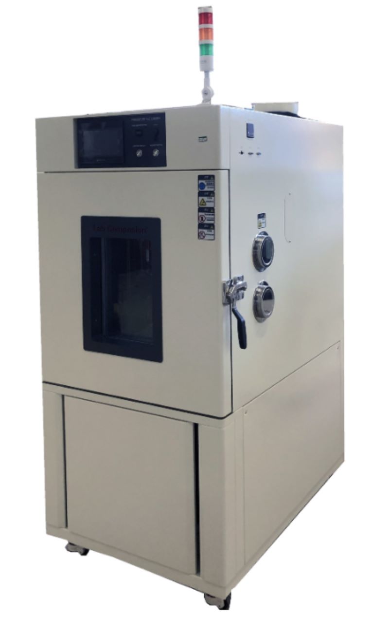
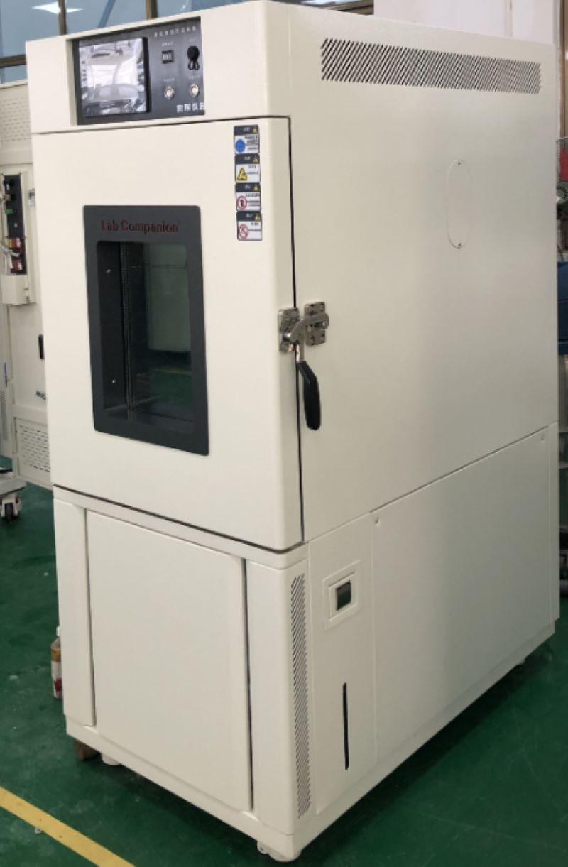
High and low temperature test chamber: Used to simulate different temperature environments.
Humidity test chamber: used to evaluate the performance of battery in humid environments.
Vibration test bench: Simulate vibration environment to evaluate the structural integrity and performance stability of battery.
Impact testing machine: used to simulate impacts in unexpected situations such as drops and collisions.
Ⅴ. Test results and evaluation
After completing the test, it is necessary to analyze and evaluate the test results. Based on test data and standard requirements, determine whether the performance of the battery meets the requirements under different environmental conditions. For undesirable battery, further analysis and corresponding improvement measures should be taken.
In summary, environmental testing of rechargeable battery is an important means to ensure their stable and reliable performance in practical use. Professional testing instruments can provide more professional, safe, scientific and effective experimental results for rechargeable battery testing, greatly reducing the cost of testing and bringing convenience to companies.
Click to check related products.
https://www.lab-companion.com/thermal-shock-test-chamber
https://www.lab-companion.com/temperature-and-humidity-chamber
https://www.lab-companion.com/rapid-temperature-cycling-test-chamber
Environmental Test Chambers-Reliability Tests
Environmental resistance test:
Temperature cycle test, temperature and humidity resistance test, impact test
Durability test:
High and low temperature preservation test, continuous switch operation test, continuous action test
Temperature cycle:
a. No boot test: 60℃/6 hours ← Rising and cooling for 30 minutes →-10℃/6 hours, 2cycle
b. Boot test: 60℃/4 hours ← Rising and cooling 30 minutes →0℃/6 hours, 2cycle, power supply without packaging and load
Temperature and humidity test:
No power test: 60℃/95%R.H./48 hours
Boot test: 60℃/95%R.H./24 hours/no packaging power supply load
Impact test: impact distance 3m, slope 15 degrees, six sides
Humidity test: 40℃/90%R.H./8 hours ←→25℃/65%R.H./16 hours, 10cycle)
High and low temperature preservation test: 60℃/95%R.H./72 hours →10℃/72 hours
Continuous switch action test:Complete the switch within one second, shut down for at least three seconds, 2000 times, 45℃/80%R.H.
Continuous action test: 40℃/85%R.H./72 hours/power on
What are the Reliability Tests for Light Emitting Diodes for Communication?
Failure determination of light emitting two tubes for communication:
Provide a fixed current to compare the optical output power, if the error is greater than 10%, the failure is determined.
Mechanical stability test:
Shock test: 5tims/axis, 1500G, 0.5ms Vibration test: 20G, 20 ~ 2000Hz, 4min/cycle, 4cycle/axis Liquid thermal shock test: 100℃(15sec)←→0℃(5sec)/5cycle
Durability test:
Accelerated aging test: 85℃/ power (maximum rated power)/5000 hours, 10000 hours
High temperature storage test: maximum rated storage temperature /2000 hours
Low temperature storage test: maximum rated storage temperature /2000 hours
Temperature cycle test: -40℃(30min)←85℃(30min), RAMP: 10/min, 500cycle
Moisture resistance test: 40℃/95%/56 days, 85℃/85%/2000 hours, sealing time
Communication diode element screening test:
Temperature screening test: 85℃/ power (maximum rated power)/96 hours screening failure determination: Compare the optical output power with the fixed current, and determine failure if the error is larger than 10%
Communication diode module screening test:
Step 1: Temperature cycle screening: -40℃(30min)←→85℃(30min), RAMP: 10/min, 20cycle, no power supply
Second: Temperature screening test: 85℃/ power (maximum rated power)/96 hours
The Role of High and Low Temperature Test Chamber for Electronic Component Testing
High and low temperature test chamber is used for electronic and electrical components, automation parts, communication components, automotive parts, metal, chemical materials, plastics and other industries, national defense industry, aerospace, military, BGA, PCB substrate wrench, electronic chip IC, semiconductor ceramic magnetic and polymer material physical changes. Testing the performance of its material to withstand high and low temperatures and the chemical changes or physical damage of the product in thermal expansion and contraction can confirm the quality of the product, from precision ics to heavy machinery components, will be an essential test chamber for product testing in various fields.
What can the high and low temperature test chamber do for electronic components? Electronic components are the foundation of the whole machine and may cause time - or stress-related failures during use due to their inherent defects or improper control of the manufacturing process. To ensure the reliability of the entire batch of components and meet the requirements of the entire system, you need to exclude the components that may have initial faults under operating conditions.
1. High temperature storage
The failure of electronic components is mostly caused by various physical and chemical changes in the body and surface, which are closely related to temperature. After the temperature rises, the chemical reaction speed is greatly accelerated, accelerating the failure process. The defective components can be exposed in time and eliminated.
High temperature screening is widely used in semiconductor devices, which can effectively eliminate failure mechanisms such as surface contamination, poor bonding and oxide layer defects. Generally stored at the highest junction temperature for 24 to 168 hours. High temperature screening is simple, inexpensive and can be carried out on many parts. After high temperature storage, the parameter performance of components can be stabilized and the parameter drift in use can be reduced.
2. Power test
In the screening, under the combined action of thermoelectric stress, many potential defects of the body and surface of the component can be well exposed, which is an important project of reliability screening. Various electronic components are usually refined for a few hours to 168 hours under rated power conditions. Some products, such as integrated circuits, can not arbitrarily change the conditions, but can use high temperature working mode to increase the working junction temperature to achieve a high stress state. Power refining requires special test equipment, high and low temperature test chamber, high cost, screening time should not be too long. Civilian products are usually a few hours, military high-reliability products can choose 100,168 hours, and aviation-grade components can choose 240 hours or longer.
3. Temperature cycle
Electronic products will encounter different ambient temperature conditions during use. Under the stress of thermal expansion and contraction, components with poor thermal matching performance are easy to fail. Temperature cycle screening utilizes the thermal expansion and contraction stress between extreme high temperature and extreme low temperature to effectively eliminate products with thermal performance defects. The commonly used component screening conditions are -55~125℃, 5~10 cycles.
Power refining requires special test equipment, high cost, screening time should not be too long. Civilian products are usually a few hours, military high-reliability products can choose 100,168 hours, and aviation-grade components can choose 240 hours or longer.
4. The necessity of screening components
The inherent reliability of electronic components depends on the reliability design of the product. In the manufacturing process of the product, due to human factors or fluctuations in raw materials, process conditions, and equipment conditions, the final product can not all achieve the expected inherent reliability. In every batch of finished products, there are always some products with some potential defects and weaknesses, which are characterized by early failure under certain stress conditions. The average life of early failed parts is much shorter than normal products.
Whether electronic equipment can work reliably depends on whether electronic components can work reliably. If the early failure parts are installed together with the whole machine equipment, the failure rate of the early failure of the whole machine equipment will be greatly increased, and its reliability will not meet the requirements, and it will also pay a huge price to repair.
Therefore, whether it is a military product or a civilian product, screening is an important means to ensure reliability. High and low temperature test chamber is the best choice for the environmental reliability test of electronic components.
Influence of Capillary Length of High and Low Temperature Test Chamber on Parameters of Refrigeration System
1. Influence on suction and exhaust temperature and pressure
With the same charge amount, the shorter the capillary, the larger the refrigerant flow rate, so the suction temperature and exhaust temperature will decrease; Similarly, when the capillary is constant, the larger the charge amount is, the larger the refrigerant flow rate is, and the suction temperature and exhaust temperature also decrease.
However, with the increase of flow, the inspiratory pressure also rises. For the exhaust pressure, the shorter the capillary is, the smaller the filling amount is. When the capillary length is constant, the higher the charge amount is, the higher it is.
2. Influence on condensing temperature and pressure
When the refrigerant charge is constant, the shorter the capillary tube is, the condensation temperature and pressure decrease.
When the capillary length is constant, the higher the charge amount, the higher the condensing temperature and pressure.
3. Influence on evaporation temperature and pressure
The shorter the capillary, the greater the evaporation temperature and pressure.
When the capillary length is constant, the higher the charge amount, the higher the evaporation temperature and pressure.
4. the influence of supercooling and superheat
When the refrigerant charge is constant, the longer the capillary is, the higher the supercooling degree and the superheat degree are.
When the capillary length is constant, the higher the charge amount, the greater the supercooling degree and the smaller the superheat degree.
5. Influence on cooling capacity, power consumption and performance coefficient EER
When the refrigerant charge is constant, the longer the capillary length, the smaller the power consumption, but the cooling capacity is also smaller, the EER is smaller.
When the charge amount increases to a certain extent, because of the influence of heat exchange temperature difference, the cooling capacity increases, and the EER also increases.
6. Design points of capillary system
(1) On the high pressure side, the reservoir is generally not used, in fact, whether the reservoir is used does not depend on what kind of throttling device, but depends on whether the operation of the entire system is needed, such as heat pump system, shutdown pump system.
(2) In the suction tube, it is best to use a gas-liquid separator.
Because when the capillary system is shut down, the high and low pressure side will balance and the evaporator will accumulate refrigerant liquid, the gas-liquid separator can prevent liquid shock and refrigerant migration.
(3) The high pressure side can accommodate all the refrigerant charged, which is to prevent the capillary blockage when the damage to the high pressure piping system and compressor.
(4) In the high load condition of the evaporator, because the capillary system can be fed back to the condenser side, the condenser should take into account whether the condensing pressure will be too high under this condition, so it is necessary to increase the condensing heat transfer area.
(5) The pipe between the condenser outlet and the capillary inlet should not accumulate refrigerant liquid.
One is that when the compressor is shut down, this part of the refrigerant liquid will evaporate because of the pressure drop, flow into the evaporator and condense, thus bringing some heat to the refrigeration space, which may have an impact on the closed space of the refrigerator, for the air conditioning, this part of the heat can be ignored;
Another is that this will delay the time of the balance of the high and low voltage side, which may cause problems when the low torque compressor starts again, which can generally be solved by increasing the delay in the control (in fact, this is also good for reducing the impact of the starting current on other electrical appliances or the grid).
(6) The capillary inlet must be filtered to prevent clogging, especially the HFC refrigerant used now, which is required to add a dryer in design.
(7) Before the refrigerant enters the capillary, it is best to have a certain degree of undercooling, which can be added to the evaporator by adding a section of undercooling tube, or generating heat exchange with the suction tube, so that the gas flash in the capillary is minimal, thereby increasing the cooling capacity and ensuring the refrigerant flow.
However, it should be noted that at low temperature conditions, the undercooling may be too large because there is a little return liquid in the suction tube, which increases the capillary flow rate, and in turn increases the undercooling degree, which may eventually cause the return liquid.
Maintenance Method of High and Low Temperature Test Chamber
There are three common types of high and low temperature test chamber controllers: software failure, system failure and hardware failure.
1, Software failure:
Software failure mainly refers to the controller failure of the high and low temperature test chamber, including the internal parameters, the control point IS control and output signal of the solenoid valve on and off.
2, System failure:
System failure refers to the initial design problems of the refrigeration system, including the leakage of refrigerant caused by high and low temperature test chamber does not cool down, and refrigerant leakage is often due to transport and high and low temperature test chamber operation jitter or refrigeration copper pipe welding process is not fine and other reasons caused.
3, Hardware failure:
Hardware failure may lead to non-cooling hardware compressor, solenoid valve and other refrigeration components.
Then the user can listen and touch to roughly understand what is the hardware high and low temperature test chamber damage, if it is a compressor failure, the compressor sound will be abnormal or do not work does not start or the compressor itself temperature is much higher than usual temperature, and the solenoid valve failure and other refrigeration components failure users are not too good to master.
In addition, the damage of the controller and the damage of the electronic parts of the control refrigeration system may also cause the phenomenon of non-cooling and non-cooling of the high and low temperature test chamber.
Scientific principle of heating and cooling of high and low temperature test chamber:
The high and low temperature test chamber has the functions of heating, cooling, humidification and dehumidification, and can detect the product's high temperature resistance, low temperature resistance and humidity resistance. How is the temperature in the high and low temperature test chamber controlled?
The heating device is the key link to control whether the high and low temperature test chamber is heated up. The controller outputs voltage to the relay when it gets the heating instruction. The high and low temperature test chamber is about 3-12 volts of direct current added to the solid state relay. The AC end of the high and low temperature test chamber is equivalent to a wire connection, and the contactor is also drawn at the same time. Heat up the constant temperature and humidity test chamber.
Cooling is an important part of the high and low temperature test chamber, which directly affects the determination of a high and low temperature and performance, including compressor, condenser, throttling device, evaporator four major components, compressor is the heart of the refrigeration system, it inhales low temperature and low pressure gas, into high temperature and high pressure gas, through condensation into a liquid to release heat, through the fan to take away heat, Therefore, the test chamber is the reason of hot air, and then become low pressure liquid through throttling, and then become low temperature and low pressure gas through the evaporator back to the compressor, the refrigerant in the evaporator to absorb the heat of the high and low temperature chamber to complete the gasification process and absorb heat, to achieve the purpose of refrigeration, to complete the high and low temperature test chamber cooling process.
High and low temperature chamber temperature and cooling rate test procedure:
In the adjustable range of the temperature of the test chamber, the lowest nominal temperature was selected as the lowest cooling temperature, and the highest nominal temperature was selected as the highest heating temperature.
Open the cold source, so that the test chamber from room temperature to the lowest cooling temperature, stable for at least 3 hours, rise to the highest heating temperature, stable for at least 3 hours and then to the lowest cooling temperature, during the heating and cooling, record once a minute, until the end of the test process.
The principle of high and low temperature test chamber heating and cooling is so, the realization of its function is completed by the setting of the control system, understanding the principle of heating and cooling, in the use of high and low temperature test chamber must be more handy.
The Measuring Principle of Hygrometer in High and Low Temperature Test Chamber
Temperature and humidity is the percentage of the amount of water vapor (vapor pressure) contained in a gas (usually air) and the amount of saturated water vapor (saturated vapor pressure) in the same case as the air, expressed in RH%. Humidity long ago had a close relationship with life, but it was difficult to quantify it. The expression of humidity is humidity, relative humidity, dew point, ratio of moisture to dry gas (weight or volume), and so on.
Humidity measurement method hygrograph humidity measurement from the principle of the division of twenty or thirty. But humidity measurement is always one of the difficult problems in the world measurement field. A seemingly simple quantity value, in depth, involves quite complex physico-chemical theoretical analysis and calculation, beginners may ignore many factors that must be paid attention to in humidity measurement, thus affecting the reasonable use of sensors.
Common humidity measurement methods are: dew point method, wet and dry bulb method and electronic sensor method, dynamic method (double pressure method, double temperature method, shunt method), static method (saturated salt method, sulfuric acid method)
1, Dew point method hygrograph: is to measure the temperature when the wet air reaches saturation, is a direct result of thermodynamics, high accuracy, wide measurement range. Precision dew point instrument for measurement can reach ±0.2°C or even higher accuracy. However, the cold mirror dew-point meter with modern optoelectric principle is expensive and often used with standard humidity generators.
2, Wet and dry bulb hygrometer: this is a wet measurement method invented in the 18th century. It has a long history and is widely used. Wet and dry bulb method is an indirect method, which converts the humidity value from the wet and dry bulb equation, and this equation is conditional: that is, the wind speed near the wet bulb must reach more than 2.5m/s. The common wet and dry bulb thermometer simplifies this condition, so its accuracy is only 5~7%RH, and the wet and dry bulb does not belong to the static method, do not simply think that improving the measurement accuracy of the two thermometers is equal to improving the measurement accuracy of the hygrometer.
3, Electronic humidity sensor method hygrometer: electronic humidity sensor products and humidity measurement belong to the industry that rose in the 1990s in recent years, at home and abroad in the field of humidity sensor research and development has made great progress. Humidity sensors are developing rapidly from simple humidity sensors to integrated, intelligent, multi-parameter detection, creating favorable conditions for the development of a new generation of humidity measurement and control systems, and also raising humidity measurement technology to a new level.
4, Double pressure method, double temperature hygrometer: is based on the thermodynamic P, V, T balance principle, the balance time is longer, shunt method is based on the precise mixing of moisture and dry air. Due to the use of modern measurement and control means, these devices can be quite precise, but because of the complex equipment, expensive, time-consuming operation, mainly used as standard measurement, its measurement accuracy can reach ±2%RH or more.
5, Static method of saturated salt hygrometer: is a common method in humidity measurement, simple and easy. However, the saturated salt method has strict requirements for the balance of liquid and gas two phases, and high requirements for the stability of ambient temperature. It requires a long time to balance, and low humidity points require even longer. Especially when the humidity difference between the indoor and the bottle is large, it needs to be balanced for 6 to 8 hours each time it is opened.
Display and Heating System of Temperature and Humidity Test Chamber
The display and control interface of temperature and humidity test chamber is intuitive and clear, and the light touch selection menu is simple and easy to use, and the performance is stable and reliable. Flexible program control, to bring users stable performance, flexible control, cost-effective products. The input channel and output channel can be expanded arbitrarily. It is a test equipment for aviation, automotive, home appliances, scientific research and other fields, used to test and determine the parameters and performance of electrical, electronic and other products and materials after temperature environment changes in high temperature, low temperature, alternating temperature and humidity degree or constant test.
Product features:
1, Use CNC cutting, laser opening, mass production test chamber.
2, Spray strictly use outdoor powder, powder is not recycled once use, strong adhesion without variegation.
3, The visual window frame is made of one-time opening mold, which has a strong industrial sense.
4, The instrument panel made of one-time mold is beautiful and generous. The label on the instrument panel uses PVC stickers and the back glue uses 3M glue.
5, The caster adopts the free adjustment height caster made by Qidong Baiyun Electronics original factory, non-market counterfeit products, high quality, beautiful and generous.
6, All the standard drawings of the refrigeration system are welded to ensure that the piping of each equipment is consistent, and the refrigeration performance has reached the appropriate state.
7, Wiring of all the standard drawings of the electrical system, thirteen inspection processes after the completion of wiring to ensure accurate wiring and no trouble.
8, The water system uses three cups to control the water level to ensure that the humidifier water supply is separated from the wet bulb water level. The temperature fluctuation caused by humidifier water is avoided.
Display:
1, The original brand temperature and humidity meter, 5.7-inch high-definition true color LCD touch screen.
2, Real-time monitoring (monitoring controller real-time data, signal point status, actual output status).
3, The controller can store the historical data within 600 days (when the temperature and humidity data are recorded at the same time at a recording interval of more than 1 minute in 24-hour operation), and can play back the uploaded historical data curve.
4, The exported files can be viewed on the computer or converted into EXCEL format by random gift software.
5, Instrument equipped with RS232/485 port.
6, With automatic calculation function, the temperature and humidity change conditions can be corrected immediately, so that the temperature and humidity control is more safe and stable.
Heating system:
1, The use of far infrared nickel alloy high-speed heating (2KW×2) electric heater;
2, High temperature independent system, does not affect low temperature test, high temperature test and alternating temperature and humidity;
3, Temperature and humidity control output power is calculated by microcomputer to achieve high precision and high efficiency.
High Pressure Failure Caused by Water Cooling Unit of High and Low Temperature Test Chamber
1, High and low temperature test chamber refrigerant charging too much. Such a thing is usually produced after the overhaul, mainly manifested as the suction and exhaust pipe working pressure, balanced working pressure are high, refrigeration compressor operation current is also high.
Solution: Air should be released under the rated load according to the working pressure and balanced working pressure of the suction and exhaust pipe and its operating current until normal.
2, The water cooling temperature of the high and low temperature test chamber is too high, and the actual condensation effect is poor. The cooling water rated load of the refrigeration unit is 40~45'C, the temperature is high, and the heat pipe is not good at heat dissipation, which must cause high condensing pressure, and this phenomenon is therefore generated in the high temperature season.
Solution: The reason for the high temperature will be: the common faults of the closed cooling tower, such as the centrifugal fan is not turned on so that the water distributor does not turn, mainly manifested in the high temperature of the cooling circulating water and the rapid rise; The average external temperature is high, the waterway is short, and the water flow of the circulating system is small, so the cooling circulating water temperature is usually maintained at a high level, and the method of upgrading the storage pool can be treated.
3, The water cooling of the high and low temperature test chamber is not enough, and the water yield cannot reach the rated value. The specific performance is that the difference of water pressure in and out of the generator set is reduced (compared with the pressure difference at the beginning of the operation of the system software fund), and the temperature difference is increased.
Solution: The reason for the insufficient water output is that the system software has less water or gas. The solution is to install an automatic exhaust valve in the upper air of the pipeline to develop the exhaust pipe; The pipeline filter is blocked or used too thin, the water permeability working capacity is limited, should use a suitable filter device and clear the q filter screen every quarter; The centrifugal pump is small and does not match the system software.
4, High and low temperature test chamber cooler fouling or blocking. Condensate water is usually used in drinking water, at about 40°C is very easy to accumulate scale, and because the closed cooling tower is vertical, it is immediately exposed to the gas, dirt and dirty things are very easy to enter the cooling system, resulting in the cooler dirty blocked, the total heat transfer area is small, low efficiency, and also harm the water output. Its main performance is that the generator set inlet and outlet water pressure difference, the temperature difference increases, the temperature of the hand cooler is very high, and the copper pipe of the cooler exhaust air conditioning is hot.
Solution: Reverse cleaning of the generator set should be carried out every quarter, and chemical cleaning scale cleaning should be carried out if necessary.
Composition of Electrical Components of High and Low Temperature Test Chamber
The main parts of high and low temperature test chamber are refrigeration units, condensers, evaporators, and controllers. The main parts play a key role, so everyone pays special attention to its main parts raw materials. However, most of them ignore its auxiliary parts at this time, or feel that the role of auxiliary parts is not worth noting. Few people want to count the specific parts, so it is not clear what specific electronic components are fully used in the constant temperature and humidity test chamber.
1, Refrigeration unit:
Used to control the operation of refrigeration unit, to carry out refrigeration cycle, and there are single-phase and three-phase.
2, Fan motor:
Used to control the fan circulation steam body, heat exchanger heat conduction, and there are indoor and outdoor.
3, Electric heater equipment:
Used for heating indoor air quality quality, tubular, flocculent points.
4, Timer:
Used for automatic control system timing boot.
5, DC contactor:
Used for refrigeration unit motor breaking and connection.
6, Leakage protector power switch:
It can not only connect or disconnect the main circuit like other switches, with the effect of leakage current detection and discrimination, when the main control circuit caused by power outage or cable sheath damage, leakage protection switch power supply main switch can be connected or disconnected switch components according to the identification results. It can be combined with isolation switch and heat relay to form a full-function low-voltage switching electronic device.
7, Overtemperature protection equipment:
Its role can not be ignored, when the controller temperature is not sensitive, the implementation of the E double maintenance of the box overtemperature, when the alarm is caused, the maintenance standby, the alarm will be different with the test temperature, relative change, you can further have the role of overtemperature maintenance. The basic concept is that when the total current flow of the broken wire exceeds the limit value, the temperature of the broken wire rises and the broken wire is broken. When the heat value caused by the broken wire does not exceed its short circuit capacity, the balance between the heat value and the released heat value is guaranteed, the temperature of the broken wire cannot reach the melting temperature, it is not easy to break.
Like this kind of small electronic components, in the high and low temperature test chamber looks innocuous, but for the structure of a test chamber is also very useful, without these components, a test chamber is not used, in short, the details determine the success of failure, fine without size, in the grasp of the test chamber at the same time, more should be from its key links to grasp.
Operation Precautions of Constant Temperature and Humidity Test Chamber
1, In order to avoid machine failure in the constant temperature and humidity test chamber, please provide power supply within the rated voltage range.
2, In order to prevent electric shock or misoperation and failure, do not switch on the power supply before the installation and wiring is finished.
3, This product is a non-explosion-proof product, please do not use the constant temperature and humidity machine in the environment with flammable or explosive gas.
4, Please try not to open the test chamber door during the work of the instrument, open at high temperature may cause hot injury to the operator, open at low temperature may cause freezing injury to the staff, and may cause freezing of the evaporator, affecting the refrigeration effect. If you must open, please do some protective work,
5, It is prohibited to disassemble, process, transform or repair the constant temperature and humidity machine without permission, otherwise there will be abnormal action, electric shock or fire risk.
6, The chamber's ventilation holes should be kept unobstructed to avoid failure, abnormal operation, reduced life and fire.
7. If the machine is damaged or deformed when unpacking, please do not use it.
8, The machine installation and setting should be careful not to let dust, wire, iron filings or other things into, otherwise wrong action or failure will occur.
9, Wiring must be correct, must be grounded. Non-grounding may cause electric shock, misoperation accidents, abnormal display or large measurement errors.
10, Regularly check the terminal screws and fixed frame, please do not use in the case of loose.
11, During the operation of the instrument, the power input terminal cover must be installed on the terminal board to prevent electric shock.
12, The instrument in operation, modify the setting, signal output, start, stop and other operations, should be fully considered before the safety, wrong operation will cause damage to the working equipment or failure.
13, Please use a dry cloth to wipe the instrument, do not use alcohol, gasoline or other organic solvents, do not splash water on the instrument, if the instrument is immersed in water, please stop use immediately, otherwise there is the risk of leakage, electric shock or fire.
14, The internal parts of the instrument have a certain life period, in order to continue to use the instrument safely, please carry out regular maintenance and maintenance. When scrapping this product, please treat it as industrial waste.
15, Before starting to check whether the power supply is stable.


 Get A Quote


 IPv6 network supported