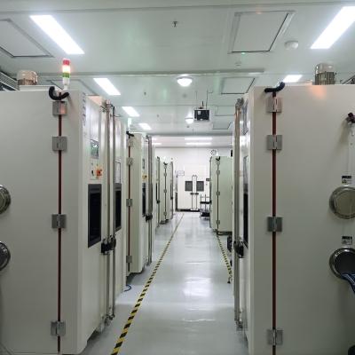
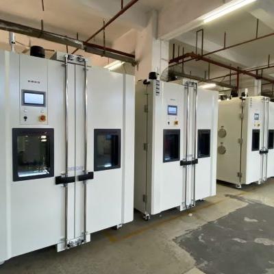
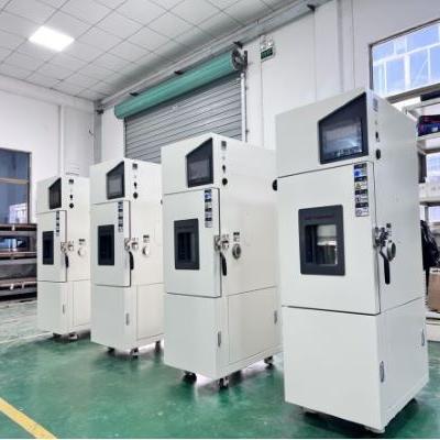
Natural Convection Test (No Wind Circulation Temperature Test) and Specification
Home entertainment audio-visual equipment and automotive electronics are one of the key products of many manufacturers, and the product in the development process must simulate the adaptability of the product to temperature and electronic characteristics at different temperatures. However, when the general oven or constant temperature and humidity test chamber is used to simulate the temperature environment, both the oven and constant temperature and humidity test chamber have a test area equipped with a circulating fan, so there will be wind speed problems in the test area. During the test, the temperature uniformity is balanced by rotating the circulating fan. Although the temperature uniformity of the test area can be achieved through the wind circulation, the heat of the product to be tested will also be taken away by the circulating air, which will be significantly inconsistent with the actual product in the wind-free use environment (such as the living room, indoor). Because of the relationship of wind circulation, the temperature difference of the product to be tested will be nearly 10 ° C, in order to simulate the actual use of environmental conditions, many people will misunderstand that only the test machine can produce temperature (such as: oven, constant temperature and humidity test chamber) can carry out natural convection test, in fact, this is not the case. In the specification, there are special requirements for wind speed, and a test environment without wind speed is required. Through the natural convection test equipment (no forced wind circulation test), the temperature environment without fan is generated (natural convection test), and then the test integration test is carried out to detect the temperature of the product under test. This solution can be applied to the actual ambient temperature test of household related electronic products or confined Spaces (such as: Large LCD TV, car cockpit, car electronics, laptop, desktop computer, game console, stereo... Etc.).
The difference of the test environment with or without wind circulation for the test of the product to be tested:
If the product to be tested is not energized, the product to be tested will not heat itself, its heat source only absorbs the air heat in the test furnace, and if the product to be tested is energized and heated, the wind circulation in the test furnace will take away the heat of the product to be tested. Every 1 meter increase in wind speed, its heat will be reduced by about 10%. Suppose to simulate the temperature characteristics of electronic products in an indoor environment without air conditioning, if an oven or a constant temperature and humidity test chamber is used to simulate 35 ° C, although the environment in the test area can be controlled within 35 ° C through electric heating and freezing, the wind circulation of the oven and the constant temperature and humidity test chamber will take away the heat of the product to be tested, making the actual temperature of the product to be tested lower than the temperature in the real state of no wind. Therefore, it is necessary to use a natural convection testing machine without wind speed to effectively simulate the actual windless environment (such as: indoor, non-starting car cockpit, instrument chassis, outdoor waterproof box... Such environment).
Indoor environment without wind circulation and solar radiant heat irradiation:
Through the natural convection tester, simulate the client's actual use of the real air conditioning convection environment, hot spot analysis and heat dissipation characteristics of the product evaluation, such as the LCD TV in the photo not only to consider its own heat dissipation, but also to evaluate the impact of thermal radiation outside the window, thermal radiation for the product may produce additional radiant heat above 35 ° C.
Comparison table of wind speed and IC product to be tested:
When the ambient wind speed is faster, the IC surface temperature will also take away the IC surface heat due to the wind cycle, resulting in faster wind speed and lower temperature, when the wind speed is 0, the temperature is 100℃, but when the wind speed reaches 5m/s, the IC surface temperature has been below 80℃.
Unforced air circulation test:
According to the specification requirements of IEC60068-2-2, in the high temperature test process, it is necessary to carry out the test conditions without forced air circulation, the test process needs to be maintained under the wind-free circulation component, and the high temperature test is carried out in the test furnace, so the test cannot be carried out through the constant temperature and humidity test chamber or oven, and the natural convection tester can be used to simulate the free air conditions.
Description of test conditions:
Test specification for unforced air circulation: IEC-68-2-2, GB2423.2, GB2423.2-89 3.3.1
Unforced air circulation test: The test condition of unforced air circulation can simulate the free air condition well
GB2423.2-89 3.1.1:
When measuring under free air conditions, when the temperature of the test sample is stable, the temperature of the most hot spot on the surface is more than 5℃ higher than the temperature of the surrounding large device, it is a heat dissipation test sample, otherwise it is a non-heat dissipation test sample.
GB2423.2-8 10(Test heat dissipation test sample temperature gradient test) :
A standard test procedure is provided to determine the adaptability of thermal electronic products (including components, equipment level other products) to use at high temperatures.
Test requirements:
a. Testing machine without forced air circulation (equipped with a fan or blower)
b. Single test sample
c. The heating rate is not greater than 1℃/min
d. After the temperature of the test sample reaches stability, the test sample is energized or the home electrical load is carried out to detect the electrical performance
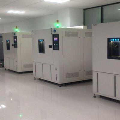
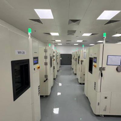
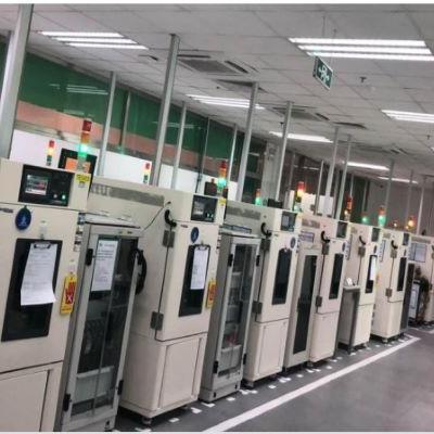
Natural convection test chamber features:
1. Can evaluate the heat output of the product to be tested after power, to provide the best distribution uniformity;
2. Combined with digital data collector, effectively measure the relevant temperature information of the product to be tested for synchronous multi-track analysis;
3. Record the information of more than 20 rails (synchronous record the temperature distribution inside the test furnace, multi-track temperature of the product to be tested, average temperature... Etc.).
4. The controller can directly display the multi-track temperature record value and record curve; Multi-track test curves can be stored on a USB drive via the controller;
5. The curve analysis software can intuitively display the multi-track temperature curve and output EXCEL reports, and the controller has three kinds of display [Complex English];
6. Multi-type thermocouple temperature sensor selection (B, E, J, K, N, R, S, T);
7. Scalable to increase heating rate & control stability planning.
Concentrator Solar Cell
A concentrating solar cell is a combination of [Concentrator Photovoltaic]+[Fresnel Lenes]+[Sun Tracker]. Its solar energy conversion efficiency can reach 31% ~ 40.7%, although the conversion efficiency is high, but due to the long sunward time, it has been used in the space industry in the past, and now it can be used in the power generation industry with sunlight tracker, which is not suitable for general families. The main material of concentrating solar cells is gallium arsenide (GaAs), that is, the three five group (III-V) materials. General silicon crystal materials can only absorb the energy of 400 ~ 1,100nm wavelength in the solar spectrum, and the concentrator is different from silicon wafer solar technology, through the multi-junction compound semiconductor can absorb a wider range of solar spectrum energy, and the current development of three-junction InGaP/GaAs/Ge concentrator solar cells can greatly improve the conversion efficiency. The three-junction concentrating solar cell can absorb energy of 300 ~ 1900nm wavelength relative to its conversion efficiency can be greatly improved, and the heat resistance of concentrating solar cells is higher than that of general wafer-type solar cells.
Polarizer Test Conditions
Polarizer is one of the basic parts of the liquid crystal display, is a light plate that only allows a certain direction of light to pass through, in the process of making the liquid crystal plate, must be used above and below each piece, and into the staggered direction placed, mainly used for electric field and no electric field when the light source produces a phase difference and the state of light and dark, to display subtitles or patterns.
Relevant test conditions:
Because the molecular structure of iodine is easy to destroy under high temperature and humidity conditions, the durability of the polarizer produced by iodine dyeing technology is poor, and generally can only meet:
High temperature: 80℃×500HR
Hot and humid: working conditions below 60℃×90%RH×500HR
However, with the expansion of the use of LCD products, the wet and hot working conditions of polarizing products are becoming more and more demanding, and there has been a demand for polarizing plate products that work at 100 ° C and 90%RH conditions, and the highest conditions at present are:
High temperature: 105℃×500HR
Humidity and heat: test requirements below 90℃×95%RH×500HR
The durability test of polarizer includes four test methods: high temperature, wet heat, low temperature and cold and heat shock, of which the most important test is the wet and heat test. The high temperature test refers to the high temperature working conditions of the polarizer at a constant baking temperature. At present, according to the technical grade of the polarizer, it is divided into:
Universal type: working temperature is 70℃×500HR;
Medium durability type: the working temperature is 80℃×500HR;
High durability type: the operating temperature is 90℃×500H above these three grades.
Because the basic materials of the polarizing film PVA film and iodine and iodide are easily hydrolyzed materials, but also because the pressure sensitive adhesive used in the polarizing plate is also easy to deteriorate under high temperature and high humidity conditions, the most important things in the environmental test of the polarizing plate are high temperature and wet heat.
Ac Solar Modules & Microinverters 1
The overall output power of the solar cell panel is greatly reduced, mainly because of some module damage (hail, wind pressure, wind vibration, snow pressure, lightning strike), local shadows, dirt, tilt Angle, orientation, different degrees of aging, small cracks... These problems will cause system configuration misalignment, resulting in reduced output efficiency defects, which are difficult to overcome traditional centralized inverters. Solar power generation cost ratio: module (40 ~ 50%), construction (20 ~ 30%), inverter (<10%), from the point of view of the cost proportion, the construction cost is as high as 1/3, if the inverter is directly installed on the module in production, the overall power generation cost can be greatly reduced.
In order to overcome such problems, in 2008 developed a microinverter (microinverter) applied to the solar module, that is, each DC solar module is equipped with a direct conversion of direct current (DC) to AC (AC) small inverter, it can be directly installed behind the module or fixed frame, Through the micro inverter tracking, each module can operate at more than 95% of the highest power point (system more than 99.5% of the time is normal operation), such an advantage is for each module to optimize the output power, so that the entire solar power system output power to obtain the highest, for the design architecture, Even if some modules are covered by shadows, heat, dust... In addition, its power transmission value is connected to AC power supply, do not need complex and professional series and parallel, direct parallel output, can also reduce the attenuation between power transmission, recent research shows that the module assembly micro-inverter can increase the energy collection by 20%, a single module provides standard AC frequency power supply, Each module has arc protection, which can reduce the probability of arc occurrence. It can be seen that the failure rate of the centralized inverter is high, it must be replaced often, and its life is only about half of the module, if we use the micro inverter its output power is lower, it can improve the service life of the inverter.
Since each module is behind the small inverter, the module does not need to configure another communication wire, can directly through the output wire of the AC Power supply, direct network communication, only need to install a power line network Bridge (Power line Ethernet Bridge) on the socket, do not need to set up another communication line, Users can directly access the web, iPhone, blackberry, tablet... Etc., watch the operation status of each module (power output, module temperature, fault message, module identification code), if there is an anomaly, it can be repaired or replaced immediately, so that the entire solar power system can operate smoothly.
Output terminal of AC module:
AC output, DC output, Control Interface
Ac solar module English name:
AC solar PV module ac pv module AC photovoltaic module AC Module PV systems composed of AC modules AC module-composed PVAC Module
Proprietary abbreviation:
CVCF: constant voltage, constant frequency
EIA(Energy Information Administration) The United States Energy Information Administration
EMC: includes EMI(Electromagnetic interference) and EMS(electromagnetic tolerance) two parts
EMI(Electromagnetic interference) : The electromagnetic noise generated by the machine itself in the process of performing the intended function is not conducive to other systems
ETL: Electronic Testing Laboratory
MFGR: Manufacturer
HALT: Highly Accelerated Life Test. Halt: highly accelerated life test
HAST(Highly Accelerated Stress Test) : Accelerated stress test
HFRE: high frequency rectifier
HFTR: high frequency transformer
MEOST[Multiple Environment Over Stress Tests] : MEOST[multiple environment over stress tests]
MIC(microinverter) : A microinverter
Micro-inverters: indicates micro-inverters
MPPT[Maximum Power Point Tracking] : indicates maximum power point tracking
MTBF: mean time between failures
NEC: National Electrical Code
PVAC Module: AC solar module
VVVF: Change voltage, change frequency
Ac Solar Modules & Microinverters 2
Ac module test specification:
ETL Certification: UL 1741, CSA Standard 22.2, CSA Standard 22.2 No. 107.1-1, IEEE 1547, IEEE 929
PV Module: UL1703
Newsletter: 47CFR, Part 15, Class B
Voltage Surge rating: IEEE 62.41 Class B
National Electrical Code: NEC 1999-2008
Arc protection devices: IEEE 1547
Electromagnetic waves: BS EN 55022, FCC Class B per CISPR 22B, EMC 89/336/EEG, EN 50081-1, EN 61000-3-2, EN 50082-2, EN 60950
Micro-Inverter (Micro-inverter) : UL1741-calss A
Typical component failure rate: MIL HB-217F
Other specifications:
IEC 503, IEC 62380 IEEE1547, IEEE929, IEEE-P929, IEEE SCC21, ANSI/NFPA-70 NEC690.2, NEC690.5, NEC690.6, NEC690.10, NEC690.11, NEC690.14, NEC690.17, NEC690.18, NEC690.64
Main specifications of AC solar module:
Operating temperature: -20℃ ~ 46℃, -40℃ ~ 60℃, -40℃ ~ 65℃, -40℃ ~ 85℃, -20 ~ 90℃
Output voltage: 120/240V, 117V, 120/208V
Output power frequency: 60Hz
Advantages of AC modules:
1. Try to increase the power generation of each inverter power module and track the maximum power, because the maximum power point of a single component is tracked, the power generation of the photovoltaic system can be greatly improved, which can be increased by 25%.
2. By adjusting the voltage and current of each row of solar panels until all are balanced, so as to avoid system mismatch.
3. Each module has monitoring function to reduce the maintenance cost of the system and make the operation more stable and reliable.
4. The configuration is flexible, and the solar cell size can be installed in the household market according to the user's financial resources.
5. No high voltage, safer to use, easy to install, faster, low maintenance and installation cost, reduce the dependence on installation service providers, so that the solar power system can be installed by users themselves.
6. The cost is similar or even lower than that of centralized inverters.
7. Easy installation (installation time reduced by half).
8. Reduce procurement and installation costs.
9. Reduce the overall cost of solar power generation.
10. No special wiring and installation program.
11. The failure of a single AC module does not affect other modules or systems.
12. If the module is abnormal, the power switch can be automatically cut off.
13. Only a simple interrupt procedure is required for maintenance.
14. Can be installed in any direction and will not affect other modules in the system.
15. It can fill the entire setting space, as long as it is placed under it.
16. Reduce the bridge between DC line and cable.
17. Reduce DC connectors (DC connectors).
18. Reduce DC ground fault detection and set protection devices.
19. Reduce DC junction boxes.
20. Reduce the bypass diode of the solar module.
21. There is no need to purchase, install and maintain large inverters.
22. No need to buy batteries.
23. Each module is installed with anti-arc device, which meets the requirements of UL1741 specification.
24. The module communicates directly through the AC power output wire without setting up another communication line.
25. 40% less components.
Ac Solar Modules & Microinverters 3
Ac module test method:
1. Output performance test: The existing module test equipment, for the non-inverter module related testing
2. Electrical stress test: Perform temperature cycle test under different conditions to evaluate the inverter's characteristics under operating temperature and standby temperature conditions
3. Mechanical stress test: find out the micro inverter with weak adhesion and the capacitor welded on the PCB board
4. Use a solar simulator for overall testing: a steady-state pulse solar simulator with large size and good uniformity is required
5. Outdoor test: Record module output I-V curve and inverter efficiency conversion curve in outdoor environment
6. Individual test: Each component of the module is tested separately in the room, and the comprehensive benefit is calculated by the formula
7. Electromagnetic interference test: Because the module has the inverter component, it is necessary to evaluate the impact on EMC&EMI when the module is running under the sunlight simulator.
Common failure causes of AC modules:
1. The resistance value is incorrect
2. The diode is inverted
3. Inverter failure causes: electrolytic capacitor failure, moisture, dust
Ac module test conditions:
HAST test: 110℃/85%R.H./206h(Sandia National Laboratory)
High temperature test (UL1741) : 50℃, 60℃
Temperature cycle: -40℃←→90℃/200cycle
Wet freezing: 85℃/85%R.H.←→-40℃/10cycles, 110 cycles(Enphase-ALT test)
Wet heat test: 85℃/85%R.H/1000h
Multiple environmental pressure tests (MEOST) : -50℃ ~ 120℃, 30G ~ 50G vibration
Waterproof: NEMA 6/24 hours
Lightning test: Tolerated surge voltage up to 6000V
Others (please refer to UL1703) : water spray test, tensile strength test, anti-arc test
Solar related Modules MTBF:
Traditional inverter 10 ~ 15years, micro inverter 331years, PV module 600years, micro inverter 600years[future]
Introduction of microinverter:
Instructions: Micro inverter (microinverter) applied to the solar module, each DC solar module is equipped with a, can reduce the probability of arc occurrence, microinverter can directly through the AC power output wire, direct network communication, Only need to install a power line Ethernet Bridge (Powerline Ethernet Bridge) on the socket, do not need to set up another communication line, users can through the computer web page, iPhone, blackberry, tablet computer... Etc., directly watch the operating state of each module (power output, module temperature, fault message, module identification code), if there is an anomaly, it can be repaired or replaced immediately, so that the entire solar power system can operate smoothly, because the micro inverter is installed behind the module, so the aging effect of ultraviolet on the micro inverter is also low.
Microinverter specifications:
UL 1741 CSA 22.2, CSA 22.2, No. 107.1-1 IEEE 1547 IEEE 929 FCC 47CFR, Part 15, Class B Compliant with the National Electric Code (NEC 1999-2008) EIA-IS-749(Corrected major application life test, specification for capacitor use)
Micro inverter test:
1. Microinverter reliability test: microinverter weight +65 pounds *4 times
2. Waterproof test of micro-inverter: NEMA 6[1 meter continuous operation in water for 24 hours]
3. Wet freezing according to IEC61215 test method: 85℃/85%R.H.←→-45℃/110 days
4. Accelerated life test of micro-inverter [110 days in total, dynamic test at rated power, has ensured that micro-inverter can last more than 20 years] :
Step 1: Wet freezing: 85℃/85%R.H.←→-45℃/10 days
Step 2: Temperature cycle: -45℃←→85℃/50 days
Step 3: Humid heat: 85℃/85%R.H./50 days
IEEE1513 Temperature Cycle Test , Humidity Freezing Test and Thermal-humidity Test 1
Among the environmental reliability test requirements of Cells, Receiver, and Module of concentrated solar cells have their own test methods and test conditions in temperature cycle test, humidity freezing test, and thermal-humidity test, and there are also differences in the quality confirmation after the test. Therefore, IEEE1513 has three tests on temperature cycle test, humidity freezing test and thermal-humidity test in the specification, and its differences and test methods are sorted out for everyone's reference.
Reference source: IEEE Std 1513-2001
IEEE1513-5.7 Thermal cycle test IEEE1513-5.7 thermal cycle test
Objective: To determine whether the receiving end can properly withstand the failure caused by the thermal expansion difference between the parts and the joint material, especially the solder joint and package quality. Background: Temperature cycling tests of concentrated solar cells reveal welding fatigue of copper heat sinks and require complete ultrasonic transmission to detect crack growth in the cells (SAND92-0958 [B5]).
Crack propagation is a function of the temperature cycle number, the initial complete solder joint, solder joint type, between the battery and the radiator due to the thermal expansion coefficient and temperature cycle parameters, after the thermal cycle test to check the receiver structure of the packaging and insulation material quality. There are two test plans for the program, tested as follows:
Program A and Program B
Procedure A: Test receiver resistance at thermal stress caused by thermal expansion difference
Procedure B: Temperature cycle before humidity freezing test
Before pretreatment, it is emphasized that the initial defects of the receiving material are caused by actual wet freezing. In order to adapt to different concentrated solar energy designs, temperature cycle tests of program A and Program B can be checked, which are listed in Table 1 and Table 2.
1. These receivers are designed with solar cells directly connected to copper radiators, and the conditions required are listed in the first row table
2. This will ensure that potential failure mechanisms, which may lead to defects occurring during the development process, are discovered. These designs adopt different methods and can use alternative conditions as shown in the table to debond the radiator of the battery.
Table 3 shows that the receiving portion performs a program B temperature cycle prior to the alternative.
Since program B mainly tests other materials on the receiving end, alternatives are offered to all designs
Table 1 - Temperature cycle procedure test for receivers
Program A- Thermal cycle
Option
Maximum temperature
Total number of cycles
Application current
Required design
TCR-A
110℃
250
No
The battery is welded directly to the copper radiator
TCR-B
90℃
500
No
Other design records
TCR-C
90℃
250
I(applied) = Isc
Other design records
Table 2 - Temperature cycle procedure test of the receiver
Procedure B- Temperature cycle before wet freezing test
Option
Maximum temperature
Total number of cycles
Application current
Required design
HFR-A
110℃
100
No
Documentation of all designs
HFR-B
90℃
200
No
Documentation of all designs
HFR-C
90℃
100
I(applied) = Isc
Documentation of all designs
Procedure: The receiving end will be subjected to a temperature cycle between -40 °C and the maximum temperature (following the test procedure in Table 1 and Table 2), the cycle test can be put into a single or two boxes of gas temperature shock test chamber, the liquid shock cycle should not be used, the dwell time is at least 10 minutes, and the high and low temperature should be within the requirement of ±5 °C. The cycle frequency should not be greater than 24 cycles a day and not less than 4 cycles a day, the recommended frequency is 18 times a day.
The number of thermal cycles and the maximum temperature required for the two samples, refer to Table 3 (Procedure B of Figure 1), after which a visual inspection and electrical characteristics test will be carried out (refer to 5.1 and 5.2). These samples will be subjected to a wet freezing test, according to 5.8, and a larger receiver will refer to 4.1.1(this procedure is illustrated in Figure 2).
Background: The purpose of the temperature cycle test is to accelerate the test that will appear in the short term failure mechanism, prior to the detection of concentrating solar hardware failure, therefore, the test includes the possibility of seeing a wide temperature difference beyond the module range, the upper limit of the temperature cycle of 60 ° C is based on the softening temperature of many module acrylic lenses, for other designs, the temperature of the module. The upper limit of the temperature cycle is 90 ° C (see Table 3)
Table 3- List of test conditions for module temperature cycles
Procedure B Temperature cycle pretreatment before wet freezing test
Option
Maximum temperature
Total number of cycles
Application current
Required design
TCM-A
90℃
50
No
Documentation of all designs
TEM-B
60℃
200
No
Plastic lens module design may be required
IEC 60068-2 Combined Condensation and Temperature and Humidity Test
In the IEC60068-2 specification, there are a total of five kinds of humid heat tests. In addition to the common 85℃/85%R.H., 40℃/93%R.H. fixed-point high temperature and high humidity, there are two more special tests [IEC60068-2-30, IEC60068-2-38], they are alternating wet and humid cycle and temperature and humidity combined cycle, so the test process will change temperature and humidity. Even multiple groups of program links and cycles applied in IC semiconductors, parts, equipment, etc. To simulate the outdoor condensation phenomenon, evaluate the material's ability to prevent water and gas diffusion, and accelerate the product's tolerance to deterioration, the five specifications are organized into a comparison table of the differences in the wet and heat test specifications, and the main points of the test are explained in detail for the wet and heat combined cycle test, and the test conditions and points of GJB in the wet and heat test are supplemented.
IEC60068-2-30 alternating humid heat cycle test
Note: This test uses the test technique of maintaining humidity and temperature alternations to make moisture permeate into the sample and produce condensation (condensation) on the surface of the product to confirm the adaptability of the component, equipment or other products in use, transportation and storage under the combination of high humidity and temperature and humidity cycle changes. This specification is also suitable for large test samples. If the equipment and the test process need to keep the power heating components for this test, the effect will be better than IEC60068-2-38, the high temperature used in this test has two (40 °C, 55 °C), the 40 °C is to meet most of the world's high temperature environment, while 55 °C meets all the world's high temperature environment, the test conditions are also divided into [cycle 1, cycle 2], In terms of severity, [Cycle 1] is higher than [Cycle 2].
Suitable for side products: components, equipment, various types of products to be tested
Test environment: the combination of high humidity and temperature cyclic changes produces condensation, and three kinds of environments can be tested [use, storage, transportation ([packaging is optional)]
Test stress: Breathing causes water vapor to invade
Whether power is available: Yes
Not suitable for: parts that are too light and too small
Test process and post-test inspection and observation: check the electrical changes after moisture [do not take out the intermediate inspection]
Test conditions: humidity: 95% R.H. warming] after [humidity maintain (25 + 3 ℃ low temperature - - high temperature 40 ℃ or 55 ℃)
Rising and cooling rate: heating (0.14℃/min), cooling (0.08~0.16℃/min)
Cycle 1: Where absorption and respiratory effects are important features, the test sample is more complex [humidity not less than 90%R.H]
Cycle 2: In the case of less obvious absorption and respiratory effects, the test sample is simpler [humidity is not less than 80%R.H.]
IEC60068-2-30 Alternating temperature and humid test (condensation test)
Note: For component types of parts products, a combination test method is used to accelerate the confirmation of the test sample's tolerance to degradation under high temperature, high humidity and low temperature conditions. This test method is different from the product defects caused by respiration [dew, moisture absorption] of IEC60068-2-30. The severity of this test is higher than that of other humid heat cycle tests, because there are more temperature changes and [respiration] during the test, and the cycle temperature range is larger [from 55℃ to 65℃]. The temperature variation rate of the temperature cycle also becomes faster [temperature rise :0.14℃/min becomes 0.38℃/min, 0.08℃/min becomes 1.16 ℃/min]. In addition, different from the general humid heat cycle, the low temperature cycle condition of -10℃ is increased, which accelerates the breathing rate and makes the water condensing in the gap of the substitute icing. Is the characteristic of this test specification, the test process allows power and load power test, but can not affect the test conditions (temperature and humidity fluctuation, rising and cooling rate) because of the heating of the side product after power, due to the change of temperature and humidity during the test process, but the top of the test chamber can not condenses water droplets to the side product.
Suitable for side products: components, metal components sealing, lead end sealing
Test environment: combination of high temperature, high humidity and low temperature conditions
Test stress: accelerated breathing + frozen water
Whether it can be powered on: it can be powered on and external electric load (it can not affect the conditions of the test chamber because of power heating)
Not applicable: Can not replace moist heat and alternating humid heat, this test is used to produce defects different from respiration
Test process and post-test inspection and observation: check the electrical changes after moisture [check under high humidity conditions and take out after test]
Test conditions: damp temperature and humidity cycle (25 ↔ 65 + 2 ° C / 93 + 3% r.h.) - low temperature cycle (25 ↔ 65 + 2 ℃ / 93 + 3% r.h. -- 10 + 2 ° C) X5 cycle = 10 cycle
Rising and cooling rate: heating (0.38℃/min), cooling (1.16 °C/min)
GJB150-o9 humid heat test
Description: The wet and heat test of GJB150-09 is to confirm the ability of equipment to withstand the influence of hot and humid atmosphere, suitable for equipment stored and used in hot and humid environment, equipment prone to high humidity storage or use, or equipment may have potential problems related to heat and humidity. Hot and humid locations may occur throughout the year in tropical areas, seasonal occurrences in mid-latitudes, and in equipment subjected to comprehensive changes in pressure, temperature and humidity. The specification specifically emphasizes 60 ° C /95%R.H. This high temperature and humidity does not occur in nature, nor does it simulate the humid and thermal effect after solar radiation, but it can find potential problems in the equipment. However, it is not possible to reproduce complex temperature and humidity environments, assess long-term effects, and reproduce humidity effects associated with low humidity environments.


 Get A Quote


 IPv6 network supported