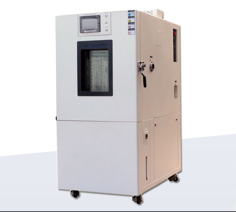
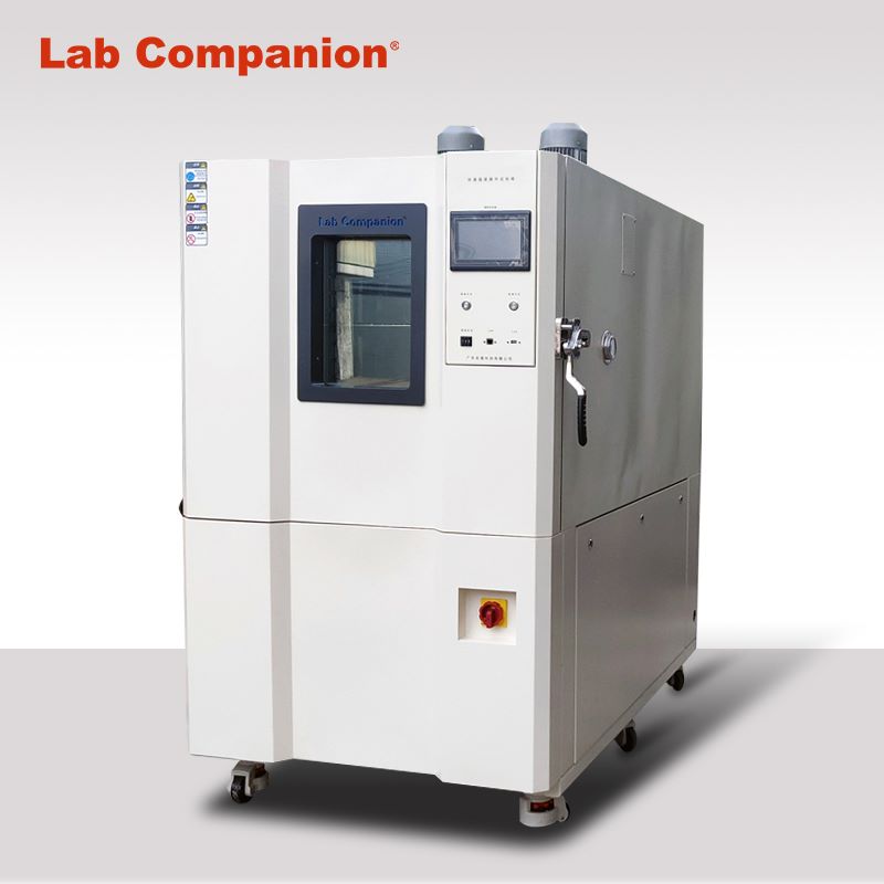
ESS Rapid Temperature Change Stress Screening Machine
Environmental Stress Screening (ESS)
Stress screening is the use of acceleration techniques and environmental stress under the design strength limit, such as: burn in, temperature cycling, random vibration, power cycle... By accelerating the stress, the potential defects in the product emerge [potential parts material defects, design defects, process defects, process defects], and eliminate electronic or mechanical residual stress, as well as eliminate stray capacitors between multi-layer circuit boards, the early death stage of the product in the bath curve is removed and repaired in advance, so that the product through moderate screening, Save the normal period and decline period of the bathtub curve to avoid the product in the process of use, the test of environmental stress sometimes lead to failure, resulting in unnecessary losses. Although the use of ESS stress screening will increase the cost and time, for improving the product delivery yield and reduce the number of repairs, there is a significant effect, but for the total cost will be reduced. In addition, customer trust will also be improved, generally for electronic parts of the stress screening methods are pre-burning, temperature cycle, high temperature, low temperature, PCB printed circuit board stress screening method is temperature cycle, for the electronic cost of the stress screening is: Power pre-burning, temperature cycling, random vibration, in addition to the stress screen itself is a process stage, rather than a test, screening is 100% of the product procedure.
Product features of rapid temperature change stress screening machine:
1, It can set different stress screening temperature variation of 5°C/min, 10°C/min and 15°C/min.
2, It can perform rapid temperature change (stress screening), condensation test, high temperature and humidity, temperature and humidity cycle and other tests.
3, It meets the requirements of electronic equipment product stress screening test.
4, It can be switched between equal temperature and average temperature two test methods.
Specification requirements of rapid temperature change stress screening machine:
1, It can set a variety of stress screening (fast temperature variability) 5°C/min, 10°C/min and 15°C/min test conditions.
2, It meets the stress screening of electronic equipment products, lead free process, MIL-STD-2164, MIL-344A-4-16, MIL-2164A-19, NABMAT-9492, GJB-1032-90, GJB/Z34-5.1.6, IPC-9701 and other test requirement.
3, It can perform equal temperature and average temperature test mode.
4, It uses aluminum sheet to verify the load capacity of the machine (non-plastic load).
High and Low Temperature Low Pressure Test Equipment & Rapid Decompression Device
High and low temperature low pressure test chamber:
(1). Main technical indicators
1. Studio size: 1000D×1000W×1000H mm, the internal size is about 1000L
2. External size: about 3400D×1400W×2010H mm, excluding the controller, test hole and other prominent parts.
3. Temperature range: -70℃ ~ +150℃
4. Temperature fluctuation: ≤±0.5℃, normal pressure, no load
5. Temperature deviation: ±2℃, normal pressure, no load
6. Temperature uniformity: ≤2℃, atmospheric pressure, no-load
7. Heating rate: +20℃→+150℃≤60min
8. Cooling rate: +20℃→-65℃≤60min
9. Humidity range: Humidity 20% ~ 98%RH (temperature +20℃ ~ +85℃ range)
10. Humidity deviation: ≤+ 2-3%RH (> 75%RH), ≤±5%RH(≤75%RH), under normal pressure and no-load conditions.
11. Pressure range: normal pressure ~ 0.5kPa
12. Pressure reduction rate: normal pressure ~ 1.0kPa≤30min
13. Pressure recovery rate: ≤10.0kPa/min
14. Pressure deviation: normal pressure ~ 40kPa:≤±2kPa, 40KPa ~ 4kPa:≤±5%kPa, below 4kPa:≤± 0.1kPa
15. Wind speed: frequency conversion adjustment
16. Power: about 50kW
17. Noise: ≤75dB (A), 1 meter away from the front of the chamber and 1.2 meters above the ground.
18. Weight: 1900Kg
(2). Rapid decompression device (optional)
In order to meet the requirements of rapid depressurization, an independent rapid depressurization chamber is processed. The rapid depressurization chamber is composed of a shell assembly, a pressure assembly, a door assembly, an interface and a moving frame. Before rapid decompression, the user needs to connect an external pipeline.
1. Studio size: 400mm deep x 500mm wide x 600mm long; The internal wall material is processed with 3.0 SUS304/2B, and 5mm square pipe is used as the pressure reinforcement.
2. External dimension: 530mm deep ×700mm wide ×880mm long, the external wall material is made of 1.2mm cold-rolled steel plate, the surface is sprayed white (consistent with the color of the chamber);
3. A pressure sensor port is reserved at the top of the container. The control sensor port is located at the rear of the container to facilitate the quick buck device to be routed.
4. For the convenience of moving fast buck device. Install four lifting casters under the frame; The moving frame is welded by ordinary steel and sprayed on the surface.
5. Rapid decompression process: In order to improve the pumping speed of rapid depressurization chamber, the test chamber is first pumped to about 1kPa, and the electric valve connecting the test chamber equipment and the fast reducing device is opened to realize the fast reducing function, and the valve is closed when it reaches 18.8kPa. The constant pressure in the fast relief chamber can be achieved by auxiliary pumping (intake valve).
(3). Product implementation standards
1. GB/T2423.1-2008 Test A: Low temperature test
2. GB/T2423.2-2008 Test B: Low temperature test
3. GB/T 2423.3-2006 test Cab: constant temperature and humidity test
4. GB/T 2423.4-2008 test Db: alternating temperature and humidity test
5. GB/T2423.21-2008 Test M: Low pressure test method
6. GB/T2423.25-2008 test Z/AM: Low temperature/low pressure comprehensive test
7. GB/T2423.26-2008 Test Z/BM: high temperature/low pressure comprehensive test
8. General requirements for GJB150.1-2009
9. GJB150.2A-2009 Low pressure (altitude) test
10. GJB150.3A-2009 high temperature test
11. GJB150.4A-2009 low temperature test
12. GJB150.6-86 temperature-height test
13. GJB150.19-86 Temperature - humidity - height test
14. DO16F rapid decompression test
15. GB/T 10586-2006 temperature and humidity test chamber technical conditions
16. GB/T 10590-2006 high temperature low pressure test chamber technical conditions
17. GB/T 10592-2008 high and low temperature test chamber technical standard
18. GB/T 5170.1-2008 General Rules for inspection methods of environmental test equipment for electrical and electronic industry
19. GB/T 5170.2-2008 Electrical and electronic products environmental test equipment test method temperature and humidity test equipment
20. GB/T 5170.5-2008 Electrical and electronic products environmental test equipment test method temperature and humidity test equipment
GB/T 5170.10-2008 Electrical and electronic products environmental test equipment test method high temperature low pressure test equipment
Thin Film Solar Cell
Thin film solar cell is a kind of solar cell manufactured by thin film technology, which has the advantages of low cost, thin thickness, light weight, flexibility and bendability. It is usually made of semiconductor materials such as copper indium gallium selenide (CIGS), cadmium telluride (CdTe), amorphous silicon, gallium arsenide (GaAs), etc. These materials have high photoelectric conversion efficiency and can generate electricity under low light conditions.
Thin film solar cells can be used in inexpensive glass, plastic, ceramics, graphite, metal sheet and other different materials as substrates to manufacture, forming a film thickness that can generate voltage only a few μm, so the amount of raw materials can be significantly reduced than silicon wafer solar cells under the same light receiving area (thickness can be lower than silicon wafer solar cells more than 90%). At present, the conversion efficiency of up to 13%, thin film solar cells are not only suitable for flat structure, because of its flexibility can also be made into non-plane structure, has a wide range of application prospects, can be combined with buildings or become a part of the building body.
Application of thin film solar cell product:
Translucent solar cell modules: Building Integrated Solar Energy Applications (BIPV)
Application of thin film solar energy: portable folding rechargeable power supply, military, travel
Applications of thin film solar modules: roofing, building integration, remote power supply, defense
Features of thin film solar cells:
1. Less power loss under the same shielding area (good power generation under weak light)
2. The loss of power under the same illumination is less than that of wafer solar cells
3. Better power temperature coefficient
4. Better light transmission
5. High cumulative power generation
6. Only a small amount of silicon is needed
7. There is no internal circuit short circuit problem (the connection has been built in the series battery manufacturing)
8. Thinner than wafer solar cells
9. Material supply is secure
10. Integrated use with building materials (BIPV)
Solar cell thickness comparison:
Crystalline silicon (200 ~ 350μm), amorphous film (0.5μm)
Types of thin film solar cells:
Amorphus Silicon (a-Si), Nanocrystalline Silicon (nc-Si), Microcrystalline Silicon, mc-Si), compound semiconductors II-IV [CdS, CdTe(cadmium telluride), CuInSe2], Dye Sensitized Solar cells, Organic/polymer solar cells, CIGS (Copper indium selenide)... Etc.
Thin-film solar module structure diagram:
Thin film solar module is composed of glass substrate, metal layer, transparent conductive layer, electrical function box, adhesive material, semiconductor layer... And so on.
Reliability test specification for thin film solar cells:
IEC61646(Thin-film solar photoelectric module test standard), CNS15115(thin-film silicon onshore solar photoelectric module design validation and type approval)
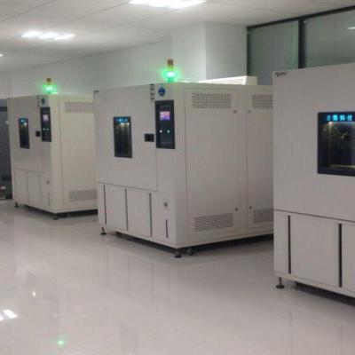
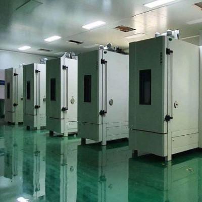
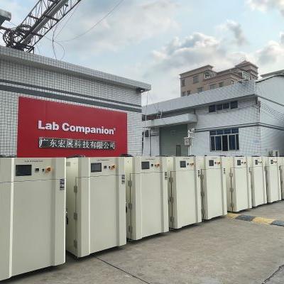
Temperature & humidity test chamber of Lab Companion
Temperature & humidity test chamber series, passed the CE certification, offer 34L, 64L, 100L, 180L, 340L, 600L, 1000L, 1500L and other volume models to meet the needs of different customers. In design, they use environment-friendly refrigerant and high-performance refrigeration system, parts and components are used in the international famous brand.
Bicycle Lamp Reliability Test
Bicycles are in the social environment of high oil prices and environmental protection, with environmental protection, fitness, slow living... Such as multi-functional recreational sports equipment, and bicycle lights are an indispensable and important part of bicycle night riding, if the purchase of low-cost and not after reliability test of bicycle lights, riding at night or through the tunnel failure, not only for the rider has a serious threat to life safety, For driving, collision accidents can occur because the driver cannot see the cyclist, so it is important to have bicycle lights that pass the reliability test.
Reasons for bicycle lamp failure:
a. Deformation, embrittlement and fading of lamp shell caused by high temperature of lamp
b. yellowing and embrittlement of lamp shell caused by outdoor ultraviolet exposure
c. Riding up and down the hill due to high and low temperature changes in the environment caused by lamp failure
d. Abnormal power consumption of car lights
e. Lights fail after a long time of rain
f. Hot failure occurs when the lights are lit for a long time
g. During riding, the lamp fixture drags loose, causing the lamp to fall
h. Lamp circuit failure caused by road vibration and slope
Bicycle lamp test classification:
Environmental test, mechanical test, radiation test, electrical test
Initial characteristic test:
Take any 30, light the lamp with DC power supply according to the rated voltage, after the characteristics are stable, measure the distance between the current and the optical center, less than 10 defective products are qualified, more than 22 are unqualified, if the number of defective products is between 11 and 22, another 100 samples are collected for testing, and the number of defective products under the original inspection is qualified when the number is less than 22. If the number exceeds 22, it is disqualified.
Life test: 10 bulbs passed the initial characteristic test, and 8 of them met the requirements.
Bicycle test speed: simulated 15 km/h environment
High temperature test (temperature test) : 80℃, 85℃, 90℃
Low temperature test: -20℃
Temperature cycle: 50℃(60min)→ normal temperature (30min)→20(60min)→ normal temperature (30min), 2cycle
Wet heat test: 30℃/95%R.H/48 hours
Stress screening test: High temperature: 85℃←→ Low temperature: -25℃, dwell time: 30min, cycle: 5cycles, power on, time: ≧24h
Shell salt spray test: 20℃/15% salt concentration/spray for 6 hours, determination method: the surface of the shell should not occur obvious rust
Waterproof test:
Description: The IPX rating of rainproof lamps needs to be at least IPX3 or above
IPX3(Water resistance) : Drop 10 liters of water vertically from a height of 200CM at 60˚ (test time: 10 minutes)
IPX4(anti-water, anti-splash) : 10 liters of water drops from 30 ~ 50CM in any direction (test time: 10 minutes)
IPX5:3m 12.5L of water from any direction [weak water](test time: 3 minutes)
IPX6:3m Strong spray 30 liters from any direction [strong water, pressure: 100KPa](test time: 3 minutes)
IPX7(Life waterproof) : It can be used for 30 minutes under 1m in water
Vibration test: vibration number 11.7 ~ 20Hz/amplitude: 11 ~ 4mm/ time: up and down 2h, about 2h, 2h before and after 2h/acceleration 4 ~ 5g
Drop test: 1 meter (hand drop), 2 meters (bicycle fall, fall from the frame)/ concrete floor/four times/four sides
Impact test: 10mm flat wooden platform/Distance: 1 m/diameter 20mm mass 36g steel ball free fall/top surface and side once
Low temperature impact: When the sample is cold to -5℃, maintain this temperature for three hours and then carry out the impact test
Irradiation test: long time irradiation brightness test, low voltage irradiation test, light brightness, light color
Bicycle lamp noun sorting:
Laptop Test Conditions
Notebook computer from the early 12-inch screen evolution to the current LED backlit screen, its computing efficiency and 3D processing, will not be lost to the general desktop computer, and the weight is becoming less and less burden, the relative reliability test requirements for the entire notebook computer is becoming more and more stringent, from the early packaging to the current boot down, the traditional high temperature and high humidity to the current condensation test. From the temperature and humidity range of the general environment to the desert test as a common condition, these are the parts that need to be considered in the production of notebook computer related components and design, the test conditions of the relevant environmental tests collected so far are organized and shared with you.
Keyboard tapping test:
Test one:
GB:1 million times
Key pressure :0.3~0.8(N)
Button stroke :0.3~1.5(mm)
Test 2: Key pressure: 75g(±10g) Test 10 keys for 14 days, 240 times per minute, a total of about 4.83 million times, once every 1 million times
Japanese manufacturers :2 to 5 million times
Taiwan manufacturer 1: more than 8 million times
Taiwan Manufacturer 2:10 million times
Power switch and connector plug pull test:
This test model simulates the lateral forces that each connector can withstand under abnormal usage. General laptop test items: USB, 1394, PS2, RJ45, Modem, VGA... Equal application force 5kg(50 times), up and down left and right pull and plug.
Power switch and connector plug test:
4000 times (Power supply)
Screen cover opening and closing test:
Taiwanese manufacturers: open and close 20,000 times
Japanese manufacturer 1: opening and closing test 85,000 times
Japanese manufacturer 2: opening and closing 30,000 times
System standby and recovery switch test:
General note type: interval 10sec, 1000cycles
Japanese manufacturer: System standby and recovery switch test 2000 times
Common causes of laptop failure:
☆ Foreign objects fall on the notebook
☆ Falls off the table while in use
☆ Tuck the notebook in a handbag or trolley case
☆ Extremely high temperature or low temperature ☆ Normal use (overuse)
☆ Wrong use in tourist destinations
☆PCMCIA inserted incorrectly
☆ Place foreign objects on the keyboard
Shutdown drop test:
General notebook type :76 cm
GB package drop: 100cm
Us Army and Japanese notebook computers: The height of the computer is 90 cm from all sides, sides, corners, a total of 26 sides
Platform :74 cm (packing required)
Land: 90cm (packing required)
TOSHIBA&BENQ 100 cm
Boot drop test:
Japanese :10 cm boot fall
Taiwan :74 cm boot fall
Laptop main board temperature shock:
Slope 20℃/min
Number of cycles 50cycles(no operation during impact)
The U.S. military's technical standards and test conditions for laptop procurement are as follows:
Impact test: Drop the computer 26 times from all sides, sides and corners at a height of 90 cm
Earthquake resistance test :20Hz~1000Hz, 1000Hz~2000Hz frequency once an hour X, Y and Z axis continuous vibration
Temperature test :0℃~60℃ 72 hours of aging oven
Waterproof test: Spray water on the computer for 10 minutes in all directions, and the water spray rate is 1mm per minute
Dust test: Spray the concentration of 60,000 mg/ per cubic meter of dust for 2 seconds (interval of 10 minutes, 10 consecutive times, time 1 hour)
Meets MIL-STD-810 military specifications
Waterproof test:
Us Army notebook :protection class:IP54(dust & rain) Sprayed the computer with water in all directions for 10 minutes at a rate of 1mm per minute.
Dust proof test:
Us Army notebook: Spray a concentration of 60,000 mg/ m3 of dust for 2 seconds (10 minute intervals, 10 consecutive times, time 1 hour)
Concentrator Solar Cell
A concentrating solar cell is a combination of [Concentrator Photovoltaic]+[Fresnel Lenes]+[Sun Tracker]. Its solar energy conversion efficiency can reach 31% ~ 40.7%, although the conversion efficiency is high, but due to the long sunward time, it has been used in the space industry in the past, and now it can be used in the power generation industry with sunlight tracker, which is not suitable for general families. The main material of concentrating solar cells is gallium arsenide (GaAs), that is, the three five group (III-V) materials. General silicon crystal materials can only absorb the energy of 400 ~ 1,100nm wavelength in the solar spectrum, and the concentrator is different from silicon wafer solar technology, through the multi-junction compound semiconductor can absorb a wider range of solar spectrum energy, and the current development of three-junction InGaP/GaAs/Ge concentrator solar cells can greatly improve the conversion efficiency. The three-junction concentrating solar cell can absorb energy of 300 ~ 1900nm wavelength relative to its conversion efficiency can be greatly improved, and the heat resistance of concentrating solar cells is higher than that of general wafer-type solar cells.
Conduction Zone of Heat
Thermal conductivity
It is the thermal conductivity of a substance, passing from high temperature to low temperature within the same substance. Also known as: thermal conductivity, thermal conductivity, thermal conductivity, heat transfer coefficient, heat transfer, thermal conductivity, thermal conductivity, thermal conductivity, thermal conductivity.
Thermal conductivity formula
k = (Q/t) *L/(A*T) k: thermal conductivity, Q: heat, t: time, L: length, A: area, T: temperature difference in SI units, the unit of thermal conductivity is W/(m*K), in imperial units, is Btu · ft/(h · ft2 · °F)
Heat transfer coefficient
In thermodynamics, mechanical engineering and chemical engineering, the heat conductivity is used to calculate the heat conduction, mainly the heat conduction of convection or the phase transformation between fluid and solid, which is defined as the heat through the unit area per unit time under the unit temperature difference, called the heat conduction coefficient of the substance, if the thickness of the mass of L, the measurement value to be multiplied by L, The resulting value is the coefficient of thermal conductivity, usually denoted as k.
Unit conversion of heat conduction coefficient
1 (CAL) = 4.186 (j), 1 (CAL/s) = 4.186 (j/s) = 4.186 (W).
The impact of high temperature on electronic products:
The rise in temperature will cause the resistance value of the resistor to decrease, but also shorten the service life of the capacitor, in addition, the high temperature will cause the transformer, the performance of the related insulation materials to decrease, the temperature is too high will also cause the solder joint alloy structure on the PCB board to change: IMC thickens, solder joints become brittle, tin whisker increases, mechanical strength decreases, junction temperature increases, the current amplification ratio of transistor increases rapidly, resulting in collector current increases, junction temperature further increases, and finally component failure.
Explanation of proper terms:
Junction Temperature: The actual temperature of a semiconductor in an electronic device. In operation, it is usually higher than the Case Temperature of the package, and the temperature difference is equal to the heat flow multiplied by the thermal resistance. Free convection (natural convection) : Radiation (radiation) : Forced Air(gas cooling) : Forced Liquid (gas cooling) : Liquid Evaporation: Surface Surroundings Surroundings
Common simple considerations for thermal design:
1 Simple and reliable cooling methods such as heat conduction, natural convection and radiation should be used to reduce costs and failures.
2 Shorten the heat transfer path as much as possible, and increase the heat exchange area.
3 When installing components, the influence of radiation heat exchange of peripheral components should be fully considered, and the thermal sensitive devices should be kept away from the heat source or find a way to use the protective measures of the heat shield to isolate the components from the heat source.
4 There should be sufficient distance between the air inlet and the exhaust port to avoid hot air reflux.
5 The temperature difference between the incoming air and the outgoing air should be less than 14 ° C.
6 It should be noted that the direction of forced ventilation and natural ventilation should be consistent as far as possible.
7 Devices with large heat should be installed as close as possible to the surface that is easy to dissipate heat (such as the inner surface of the metal casing, metal base and metal bracket, etc.), and there is good contact heat conduction between the surface.
8 Power supply part of the high-power tube and rectifier bridge pile belong to the heating device, it is best to install directly on the housing to increase the heat dissipation area. In the layout of the printed board, more copper layers should be left on the board surface around the larger power transistor to improve the heat dissipation capacity of the bottom plate.
9 When using free convection, avoid using heat sinks that are too dense.
10 The thermal design should be considered to ensure that the current carrying capacity of the wire, the diameter of the selected wire must be suitable for the conduction of the current, without causing more than the allowable temperature rise and pressure drop.
11 If the heat distribution is uniform, the spacing of the components should be uniform to make the wind flow evenly through each heat source.
12 When using forced convection cooling (fans), place the temperature-sensitive components closest to the air intake.
13 The use of free convection cooling equipment to avoid arranging other parts above the high power consumption parts, the correct approach should be uneven horizontal arrangement.
14 If the heat distribution is not uniform, the components should be sparsely arranged in the area with large heat generation, and the component layout in the area with small heat generation should be slightly denser, or add a diversion bar, so that the wind energy can effectively flow to the key heating devices.
15 The structural design principle of the air inlet: on the one hand, try to minimize its resistance to the air flow, on the other hand, consider dust prevention, and comprehensively consider the impact of the two.
16 Power consumption components should be spaced as far apart as possible.
17 Avoid crowding temperature sensitive parts together or arranging them next to high power consuming parts or hot spots.
18 The use of free convection cooling equipment to avoid arranging other parts above the high power consumption parts, the correct practice should be uneven horizontal arrangement.
Temperature Cyclic Stress Screening (1)
Environmental Stress Screening (ESS)
Stress screening is the use of acceleration techniques and environmental stress under the design strength limit, such as: burn in, temperature cycling, random vibration, power cycle... By accelerating the stress, the potential defects in the product emerge [potential parts material defects, design defects, process defects, process defects], and eliminate electronic or mechanical residual stress, as well as eliminate stray capacitors between multi-layer circuit boards, the early death stage of the product in the bath curve is removed and repaired in advance, so that the product through moderate screening, Save the normal period and decline period of the bathtub curve to avoid the product in the process of use, the test of environmental stress sometimes lead to failure, resulting in unnecessary losses. Although the use of ESS stress screening will increase the cost and time, for improving the product delivery yield and reduce the number of repairs, there is a significant effect, but for the total cost will be reduced. In addition, customer trust will also be improved, generally for electronic parts of the stress screening methods are pre-burning, temperature cycle, high temperature, low temperature, PCB printed circuit board stress screening method is temperature cycle, for the electronic cost of the stress screening is: Power pre-burning, temperature cycling, random vibration, in addition to the stress screen itself is a process stage, rather than a test, screening is 100% of the product procedure.
Stress screening applicable product stage: R & D stage, mass production stage, before delivery (screening test can be carried out in components, devices, connectors and other products or the whole machine system, according to different requirements can have different screening stress)
Stress screening comparison:
a. Constant high temperature pre-burning (Burn in) stress screening, is the current electronic IT industry commonly used method to precipitate electronic components defects, but this method is not suitable for screening parts (PCB, IC, resistor, capacitor), According to statistics, the number of companies in the United States that use temperature cycling to screen parts is five times more than the number of companies that use constant high temperature prefiring to screen components.
B. GJB/DZ34 indicates the proportion of temperature cycle and random vibrating screen selection defects, temperature accounted for about 80%, vibration accounted for about 20% of the defects in various products.
c. The United States has conducted a survey of 42 enterprises, random vibration stress can screen out 15 to 25% of the defects, while the temperature cycle can screen out 75 to 85%, if the combination of the two can reach 90%.
d. The proportion of product defect types detected by temperature cycling: insufficient design margin: 5%, production and workmanship errors: 33%, defective parts: 62%
Description of fault induction of temperature cyclic stress screening:
The cause of product failure induced by temperature cycling is: when the temperature is cycled within the upper and lower extremal temperatures, the product produces alternating expansion and contraction, resulting in thermal stress and strain in the product. If there is a transient thermal ladder (temperature non-uniformity) within the product, or the thermal expansion coefficients of adjacent materials within the product do not match each other, these thermal stresses and strains will be more drastic. This stress and strain is greatest at the defect, and this cycle causes the defect to grow so large that it can eventually cause structural failure and generate electrical failure. For example, a cracked electroplated through-hole eventually cracks completely around it, causing an open circuit. Thermal cycling enables soldering and plating through holes on printed circuit boards... Temperature cyclic stress screening is especially suitable for electronic products with printed circuit board structure.
The fault mode triggered by the temperature cycle or the impact on the product is as follows:
a. The expansion of various microscopic cracks in the coating, material or wire
b. Loosen poorly bonded joints
c. Loosen improperly connected or riveted joints
d. Relax the pressed fittings with insufficient mechanical tension
e. Increase the contact resistance of poor quality solder joints or cause an open circuit
f. Particle, chemical pollution
g. Seal failure
h. Packaging issues, such as bonding of protective coatings
i. Short circuit or open circuit of the transformer and coil
j. The potentiometer is defective
k. Poor connection of welding and welding points
l. Cold welding contact
m. Multi-layer board due to improper handling of open circuit, short circuit
n. Short circuit of power transistor
o. Capacitor, transistor bad
p. Dual row integrated circuit failure
q. A box or cable that is nearly short-circuited due to damage or improper assembly
r. Breakage, breakage, scoring of material due to improper handling... Etc.
s. out-of-tolerance parts and materials
t. resistor ruptured due to lack of synthetic rubber buffer coating
u. The transistor hair is involved in the grounding of the metal strip
v. Mica insulation gasket rupture, resulting in short circuit transistor
w. Improper fixing of the metal plate of the regulating coil leads to irregular output
x. The bipolar vacuum tube is open internally at low temperature
y. Coil indirect short circuit
z. Ungrounded terminals
a1. Component parameter drift
a2. Components are improperly installed
a3. Misused components
a4. Seal failure
Introduction of stress parameters for temperature cyclic stress screening:
The stress parameters of temperature cyclic stress screening mainly include the following: high and low temperature extremum range, dwell time, temperature variability, cycle number
High and low temperature extremal range: the larger the range of high and low temperature extremal, the fewer cycles required, the lower the cost, but can not exceed the product can withstand the limit, do not cause new fault principle, the difference between the upper and lower limits of temperature change is not less than 88°C, the typical range of change is -54°C to 55°C.
Dwell time: In addition, the dwell time can not be too short, otherwise it is too late to make the product under test produce thermal expansion and contraction stress changes, as for the dwell time, the dwell time of different products is different, you can refer to the relevant specification requirements.
Number of cycles: As for the number of cycles of temperature cyclic stress screening, it is also determined by considering product characteristics, complexity, upper and lower limits of temperature and screening rate, and the screening number should not be exceeded, otherwise it will cause unnecessary harm to the product and cannot improve the screening rate. The number of temperature cycles ranges from 1 to 10 cycles [ordinary screening, primary screening] to 20 to 60 cycles [precision screening, secondary screening], for the removal of the most likely workmanship defects, about 6 to 10 cycles can be effectively removed, in addition to the effectiveness of the temperature cycle, Mainly depends on the temperature variation of the product surface, rather than the temperature variation inside the test box.
There are seven main influencing parameters of temperature cycle:
(1) Temperature Range
(2) Number of Cycles
(3) Temperature Rate of Chang
(4) Dwell Time
(5) Airflow Velocities
(6) Uniformity of Stress
(7) Function test or not (Product Operating Condition)
IEC 60068-2
Instructions:
IEC(International Electrotechnical Association) is the world's oldest non-governmental international electrical standardization organization, for the people's livelihood of the electronic products to develop relevant test specifications and methods, such as: mainframe board, notebook computers, tablets, smartphones, LCD screens, game consoles... The main spirit of its test is extended from IEC, the main representative of which is IEC60068-2, environmental test conditions its [environmental test] refers to the sample exposed to natural and artificial environments, but the performance of its actual use, transportation and storage conditions are evaluated. The environmental test of the sample can be uniform and linear through the use of standardized standards. Environmental testing can simulate whether the product can adapt to environmental changes (temperature, humidity, vibration, temperature change, temperature shock, salt spray, dust) at different stages (storage, transport, use). And verify that the characteristics and quality of the product itself will not be affected by it, low temperature, high temperature, temperature impact can produce mechanical stress, this stress makes the test sample more sensitive to the subsequent test, impact, vibration can produce mechanical stress, this stress can make the sample immediately damaged, air pressure, alternating humid heat, constant humid heat, corrosion application of these tests and can be continued thermal and mechanical stress test effects.
Important IEC specification sharing:
IEC69968-2-1- Cold
Test purpose: To test the ability of automotive components, equipment or other component products to operate and store at low temperatures.
Test methods are divided into:
1.Aa: Temperature sudden change method for non-thermal specimens
2.Ab: Temperature gradient method for non-thermal specimens
3.Ad: Temperature gradient method of thermogenic specimen
Note:
Aa:
1. Static test (without power supply).
2. First cool down to the specified temperature of the specification before placing the test part.
3. After stability, the temperature difference of each point on the specimen does not exceed ±3℃.
4. After the test is completed, the specimen is placed under standard atmospheric pressure until the fog is completely removed: no voltage is added to the specimen during the transfer process.
5. Measure after returning to the original condition (at least 1hr).
Ab:
1. Static test (without power supply).
2. The specimen is placed in the cabinet at room temperature, and the temperature change of the cabinet temperature does not exceed 1℃ per minute.
3. The specimen shall be kept in the cabinet after the test, and the temperature change of the cabinet temperature shall not exceed 1℃ per minute to return to the standard atmospheric pressure; The specimen should not be charged during temperature change.
4. Measure after returning to the original condition (at least 1hr). (The difference between the temperature and the air temperature is more than 5℃).
Ac:
1. Dynamic test (plus power supply) when the temperature of the specimen is stable after charging, the temperature of the specimen surface is the most hot spot.
2. The specimen is placed in the cabinet at room temperature, and the temperature change of the cabinet temperature does not exceed 1℃ per minute.
3. The specimen should be kept in the cabinet after the test, and the temperature change of the cabinet temperature should not exceed 1℃ per minute, and return to the standard atmospheric pressure; The specimen should not be charged during temperature change.
4. Measure after returning to the original condition (at least 1hr).
Test conditions:
1. Temperature :-65,-55,-40,-25,-10,-5,+5°C
2. Resident time :2/16/72/96 hours.
3. Temperature variation rate: no more than 1℃ per minute.
4. Tolerance error :+3°C.
Test setup:
1. Heat generating specimens should be placed in the center of the test cabinet and the wall of the cabinet > 15cm
Sample to specimen > 15cm test cabinet to test volume ratio > 5:1.
2. For heat-generating specimens, if air convection is used, the flow rate should be kept to a minimum.
3. The specimen should be unpacked, and the fixture should have the characteristics of high heat conduction.
IEC 60068-2-2- Dry heat
Test purpose: To test the ability of components, equipment or other component products to operate and store in high temperature environments.
The test method is:
1. Ba: Temperature sudden change method for non-thermal specimens
2.Bb: Temperature gradient method for non-thermal specimens
3.Bc: Temperature sudden change method for thermogenic specimens
4.Bd: Temperature gradient method for thermogenic specimens
Note:
Ba:
1. Static test (without power supply).
2. First cool down to the specified temperature of the specification before placing the test part.
3. After stability, the temperature difference of each point on the specimen does not exceed +5℃.
4. After the test is completed, place the specimen under standard atmospheric pressure and return to the original condition (at least 1hr).
Bb:
1. Static test (without power supply).
2. The specimen is placed in the cabinet at room temperature, and the temperature change of the cabinet temperature does not exceed 1℃ per minute, and the temperature is reduced to the temperature value specified in the specification.
3. The specimen shall be kept in the cabinet after the test, and the temperature change of the cabinet temperature shall not exceed 1℃ per minute to return to the standard atmospheric pressure; The specimen should not be charged during temperature change.
4. Measure after returning to the original condition (at least 1hr).
Bc:
1. Dynamic test (external power supply) When the temperature of the specimen is stable after charging, the difference between the temperature of the hottest spot on the surface of the specimen and the air temperature is more than 5℃.
2. Heat up to the specified temperature of the specification before placing the test part.
3. After stability, the temperature difference of each point on the specimen does not exceed +5℃.
4. After the test is completed, the specimen will be placed under the standard atmospheric pressure, and the measurement will be carried out after the original condition is returned (at least 1hr).
5. The average temperature of the decimal point on the plane of 0~50mm on the bottom surface of the specimen.
Bd:
1. Dynamic test (external power supply) when the temperature of the specimen is stable after charging, the temperature of the most hot spot on the surface of the specimen is more than 5°C different from the air temperature.
2. The specimen is placed in the cabinet at room temperature, and the temperature change of the cabinet temperature does not exceed 1℃ per minute, and rises to the specified temperature value.
3. Return to standard atmospheric pressure; The specimen should not be charged during temperature change.
4. Measure after returning to the original condition (at least 1hr).
Test conditions:
1. The temperature 1000,800,630,500,400,315,250,200,175,155,125,100,85,70,55,40,30 ℃.
1. Resident time: 2/16/72/96 hours.
2. Temperature variation rate: no more than 1℃ per minute. (Average in 5 minutes)
3. Tolerance error: tolerance of ±2℃ below 200℃. (200~1000℃ tolerance ±2%)
IEC 60068-2-2- Test method Ca: Steady damp heat
1. Test purpose:
The purpose of this test method is to determine the adaptability of components, equipment or other products to operation and storage at constant temperature and high relative humidity.
Step 2: Scope
This test method can be applied to both heat-dissipating and non-heat-dissipating specimens.
3. No limits
4. Test steps:
4.1 Specimens shall be inspected visually, electrically and mechanically in accordance with relevant specifications before testing.
4.2 The test specimen must be placed in the test cabinet in accordance with the relevant specifications. In order to avoid the formation of water droplets on the test specimen after it is placed in the cabinet, it is best to preheat the temperature of the test specimen to the temperature condition in the test cabinet in advance.
4.3 The specimen shall be insulated in accordance with the specified residence.
4.4 If specified in the relevant specifications, functional tests and measurements shall be performed during or after the test, and the functional tests shall be performed in accordance with the cycle required in the specifications, and the test pieces shall not be moved out of the test cabinet.
4.5 After the test, the specimen must be placed under standard atmospheric conditions for at least one hour and at most two hours to return to its original condition. Depending on the characteristics of the specimen or the different laboratory energy, the specimen can be removed or retained in the test cabinet to wait for recovery, if you want to remove the time to be as short as possible, preferably not more than five minutes, if maintained in the cabinet the humidity must be reduced to 73% to 77% R.H. within 30 minutes, while the temperature must also reach the laboratory temperature within 30 minutes +1℃ range.
5. Test conditions
5.1 Test temperature: The temperature in the test cabinet should be controlled within the range of 40+2°C.
5.2 Relative humidity: The humidity in the test cabinet should be controlled at 93(+2/-3)% R.H. Within the range.
5.3 Resident time: The resident time can be 4 days, 10 days, 21 days or 56 days.
5.4 Test tolerance: temperature tolerance is +2℃, error of packet content measurement, slow change of temperature and temperature difference in the temperature cabinet. However, in order to facilitate the maintenance of humidity within a certain range, the temperature of any two points in the test cabinet should be maintained within the minimum range as far as possible at any time. If the temperature difference exceeds 1 ° C, the humidity changes beyond the permissible range. Therefore, even short-term temperature changes may need to be controlled within 1 ° C.
6. Test setup
6.1 Temperature and humidity sensing devices must be installed in the test cabinet to monitor the temperature and humidity in the cabinet.
6.2 There shall be no condensation water droplets on the test specimen at the top or wall of the test cabinet.
6.3 The condensed water in the test cabinet must be discharged continuously and shall not be used again unless it is purified (re-purifed).
6.4 When the humidity in the test cabinet is achieved by spraying water into the test cabinet, the moisture resistance coefficient shall not be less than 500Ω.
7. Other
7.1 The temperature and humidity conditions in the test cabinet must be uniform and similar to those in the vicinity of the temperature and humidity sensor.
7.2 The temperature and humidity conditions in the test cabinet shall not be changed during the power-on or functional test of the specimen.
7.3 Precautions to be taken when removing moisture from the specimen surface shall be detailed in the relevant specifications.
IEC 68-2-14 Test method N: Temperature variation
1. Test purpose
The purpose of this test method is to determine the effect of the specimen on the environment of temperature change or continuous temperature change.
Step 2: Scope
This test method can be divided into:
Test method Na: Rapid temperature change within a specified time
Test method Nb: Temperature change at specified temperature variability
Test method Nc: Rapid temperature change by double liquid immersion method.
The first two items apply to components, equipment or other products, and the third item applies to glass-metal seals and similar products.
Step 3 Limit
This test method does not validate high or low temperature environmental effects, and if such conditions are to be validated, "IEC68-2-1 test Method A:" cold "or "IEC 60068-2-2 Test Method B: dry heat" should be used.
4. Test procedure
4.1 Test method Na:
Rapid temperature change in a specific time
4.1.1 Specimens shall be inspected visually, electrically and mechanically in accordance with relevant specifications before testing.
4.1.2 The specimen type shall be unpacked, unpowered and ready for use or other conditions specified in relevant specifications. The initial condition of the specimen was room temperature in the laboratory.
4.1.3 Adjust the temperature of the two temperature cabinets respectively to the specified high and low temperature conditions.
4.1.4 Place the specimen in the low-temperature cabinet and keep it warm according to the specified residence time.
4.1.5 Move the specimen into the high-temperature cabinet and keep it warm according to the specified residence time.
4.1.6 The transfer time of high and low temperature shall be subject to the test conditions.
4.1.7 Repeat the procedure of Steps 4.1.4 and 4.1.5 four times
4.1.8 After the test, the specimen should be placed under standard atmospheric conditions and kept for a certain time to make the specimen reach temperature stability. The response time shall refer to the relevant regulations.
4.1.9 After the test, the specimens shall be inspected visually, electrically and mechanically in accordance with relevant specifications.
4.2 Test method Nb:
Temperature change at a specific temperature variability
4.2.1 The specimens shall be inspected visually, electrically and mechanically in accordance with relevant specifications before testing.
4.2.2 Place the test piece in the temperature cabinet. The shape of the test piece should be unpacked, unpowered and ready for use or other conditions specified in relevant specifications. The initial condition of the specimen was room temperature in the laboratory.
The specimen can be made operational if required by the relevant specification.
4.2.3 The temperature of the cabinet shall be lowered to the prescribed low temperature condition, and the insulation shall be carried out according to the prescribed residence time
4.2.4 The temperature of the cabinet shall be raised to the specified high temperature condition, and heat preservation shall be carried out according to the specified residence time
4.2.5 The temperature variability of high and low temperature shall be subject to the test conditions.
4.2.6 Repeat the procedure in Steps 4.2.3 and 4.2.4:
Electrical and mechanical tests shall be performed during the test.
Record the time used for electrical and mechanical testing.
After the test, the specimen should be placed under standard atmospheric conditions and kept for a certain time to make the specimen reach the temperature stability recovery time referred to the relevant specifications.
After the test, the specimens shall be inspected visually, electrically and mechanically in accordance with the relevant specifications
5. Test conditions
Test conditions can be selected by the following appropriate temperature conditions and test time or in accordance with the relevant specifications,
5.1 Test method Na:
Rapid temperature change in a specific time
High temperature: 1000800630500400315250200175155125100,85,70,55,4030 ° C
Low temperature :-65,-55,-40,-25.-10.-5 °C
Humidity: Vapor content per cubic meter of air should be less than 20 grams (equivalent to 50% relative humidity at 35 ° C).
Residence time: The temperature adjustment time of the temperature cabinet can be 3 hours, 2 hours, 1 hour, 30 minutes or 10 minutes, if there is no provision, it is set to 3 hours. After the test piece is placed in the temperature cabinet, the temperature adjustment time cannot exceed one-tenth of the residence time. Transfer time: manual 2~3 minutes, automatic less than 30 seconds, small specimen less than 10 seconds.
Number of cycles :5 cycles.
Test tolerance: The tolerance of temperature below 200℃ is +2℃
The tolerance of the temperature between 250 and 1000C is +2% of the test temperature. If the size of the temperature cabinet cannot meet the above tolerance requirements, the tolerance can be relaxed: the tolerance of the temperature below 100 ° C is ±3 ° C, and the tolerance of the temperature between 100 and 200 ° C is ±5 ° C (the tolerance relaxation should be indicated in the report).
5.2 Test method Nb:
Temperature change at a specific temperature variability
High temperature: 1000800630500400315250200175155125100,85,70 55403 0 'C
Low temperature :-65,-55,-40,-25,-10,-5,5℃
Humidity: Vapor per cubic meter of air should be less than 20 grams (equivalent to 50% relative humidity at 35 ° C) Residence time: including rising and cooling time can be 3 hours, 2 hours, 1 hour, 30 minutes or 10 minutes, if there is no provision, set to 3 hours.
Temperature variability: The average temperature fluctuation of the temperature cabinet within 5 minutes is 1+0.2 ° C /min, 3+0.6 ° C /min, or 5+1 ° C /min.
Number of cycles :2 cycles.
Test tolerance: The tolerance of temperature below 200℃ is +2℃.
The tolerance of the temperature between 250 and 1000℃C is +2% of the test temperature. If the size of the temperature cabinet cannot meet the above tolerance requirements, the tolerance can be relaxed. The tolerance of the temperature below 100 ° C is +3 ° C. The temperature between 100 ° C and 200 ° C is +5 ° C. (The tolerance relaxation should be indicated in the report).
6. Test setup
6.1 Test method Na:
Rapid temperature change in a specific time
The difference between the inner wall temperature of the high and low temperature cabinets and the temperature test specifications shall not exceed 3% and 8%(shown in °K) respectively to avoid thermal radiation problems.
The thermogenic specimen should be placed in the center of the test cabinet as far as possible, and the distance between the specimen and the cabinet wall, the specimen and the specimen should be greater than 10 cm, and the ratio of the volume of the temperature cabinet and the specimen should be greater than 5:1.
6.2 Test method Nb:
Temperature change at a specific temperature variability
Specimens shall be inspected visually, electrically and mechanically in accordance with relevant specifications before testing.
The specimen shall be in unpacked, unpowered and ready for use condition or other conditions specified in relevant specifications. The initial condition of the specimen was room temperature in the laboratory.
Adjust the temperature of the two temperature cabinets respectively to the specified high and low temperature conditions
The specimen is placed in a low-temperature cabinet and kept warm according to the specified residence time
The specimen is placed in a high temperature cabinet and insulated according to the specified residence time.
The transfer time of high and low temperature shall be performed according to the test conditions.
Repeat the procedure of steps d and e four times.
After the test, the specimen should be placed under standard atmospheric conditions and kept for a certain time to make the specimen reach the temperature stability recovery time referred to the relevant specifications.
After the test, the specimens shall be inspected visually, electrically and mechanically in accordance with the relevant specifications
6.3 Test method NC:
Rapid temperature change of double liquid soaking method
The liquid used in the test shall be compatible with the specimen and shall not harm the specimen.
7. Others
7.1 Test method Na:
Rapid temperature change in a specific time
When the specimen is placed in the temperature cabinet, the temperature and air flow rate in the cabinet must reach the specified temperature specification and tolerance within one-tenth of the holding time.
The air in the cabinet must be maintained in a circle, and the air flow rate near the specimen must not be less than 2 meters per second (2m/s).
If the specimen is transferred from the high or low temperature cabinet, the holding time cannot be completed for some reason, it will stay in the previous holding state (preferably at low temperature).
7.2 Test method Nb:
The air in the cabinet must be maintained in a circle at a specific temperature variability, and the air flow rate near the specimen must not be less than 2 meters per second (2m/s).
7.3 Test method NC:
Rapid temperature change of double liquid soaking method
When the specimen is immersed in the liquid, it can be quickly transferred between the two containers, and the liquid cannot be stirred.
What are the Safety Protection Systems of the High and Low Temperature Test Chamber?
1, Leakage/surge protection:Leakage circuit breaker leakage protection FUSE.RC electronic surge protection from Taiwan
2, The controller internal self-automatic detection and protection device
(1) Temperature/humidity sensor: The controller controls the temperature and humidity in the test area within the set range through the temperature and humidity sensor
(2) Controller overtemperature alarm: when the heating tube in the chamber continues to heat up and exceeds the temperature set by the internal parameters of the controller, the buzzer in it will alarm and need to be manually reset and reused
3, Fault detection control interface: external fault automatic detection protection Settings
(1) The first layer of high temperature overtemperature protection: operation control overtemperature protection Settings
(2) The second layer of high temperature and overtemperature protection: the use of anti-dry burning overtemperature protector to protect the system will not be heated all the time to burn the equipment
(3) Water break and air burning protection: humidity is protected by anti-dry burning overtemperature protector
(4) Compressor protection: refrigerant pressure protection and over-load protection device
4, Fault abnormal protection: when the fault occurs, cut off the control power supply and the fault cause indication and alarm output signal
5, Automatic water shortage warning: the machine water shortage active warning
6, Dynamic high and low temperature protection: with the setting conditions to dynamically adjust the high and low temperature protection value


 Get A Quote


 IPv6 network supported