What are the Reliability Tests for Light Emitting Diodes for Communication?
Failure determination of light emitting two tubes for communication:
Provide a fixed current to compare the optical output power, if the error is greater than 10%, the failure is determined.
Mechanical stability test:
Shock test: 5tims/axis, 1500G, 0.5ms Vibration test: 20G, 20 ~ 2000Hz, 4min/cycle, 4cycle/axis Liquid thermal shock test: 100℃(15sec)←→0℃(5sec)/5cycle
Durability test:
Accelerated aging test: 85℃/ power (maximum rated power)/5000 hours, 10000 hours
High temperature storage test: maximum rated storage temperature /2000 hours
Low temperature storage test: maximum rated storage temperature /2000 hours
Temperature cycle test: -40℃(30min)←85℃(30min), RAMP: 10/min, 500cycle
Moisture resistance test: 40℃/95%/56 days, 85℃/85%/2000 hours, sealing time
Communication diode element screening test:
Temperature screening test: 85℃/ power (maximum rated power)/96 hours screening failure determination: Compare the optical output power with the fixed current, and determine failure if the error is larger than 10%
Communication diode module screening test:
Step 1: Temperature cycle screening: -40℃(30min)←→85℃(30min), RAMP: 10/min, 20cycle, no power supply
Second: Temperature screening test: 85℃/ power (maximum rated power)/96 hours
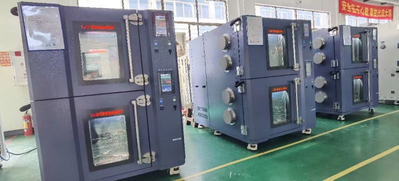
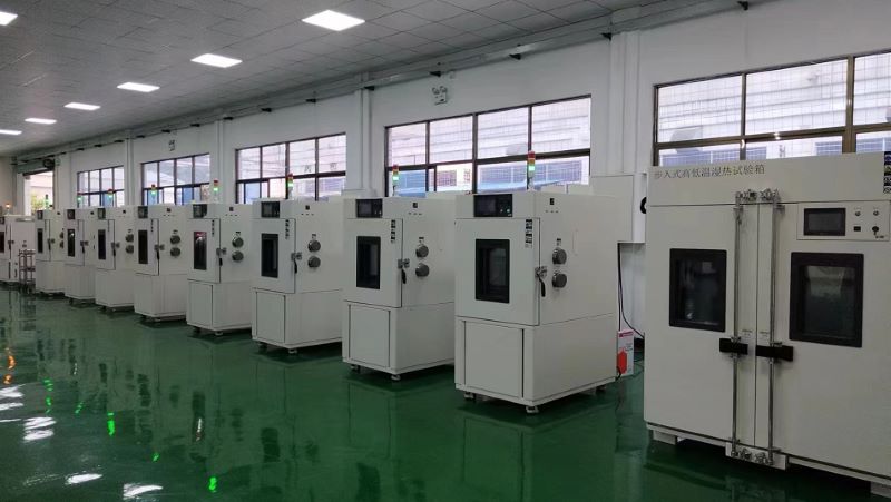
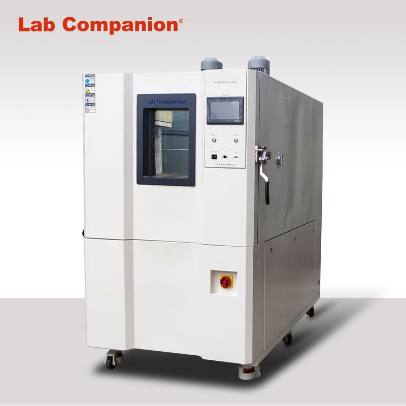
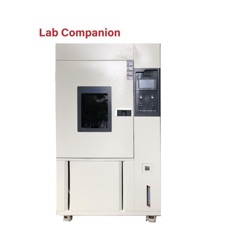
Display and Heating System of Temperature and Humidity Test Chamber
The display and control interface of temperature and humidity test chamber is intuitive and clear, and the light touch selection menu is simple and easy to use, and the performance is stable and reliable. Flexible program control, to bring users stable performance, flexible control, cost-effective products. The input channel and output channel can be expanded arbitrarily. It is a test equipment for aviation, automotive, home appliances, scientific research and other fields, used to test and determine the parameters and performance of electrical, electronic and other products and materials after temperature environment changes in high temperature, low temperature, alternating temperature and humidity degree or constant test.
Product features:
1, Use CNC cutting, laser opening, mass production test chamber.
2, Spray strictly use outdoor powder, powder is not recycled once use, strong adhesion without variegation.
3, The visual window frame is made of one-time opening mold, which has a strong industrial sense.
4, The instrument panel made of one-time mold is beautiful and generous. The label on the instrument panel uses PVC stickers and the back glue uses 3M glue.
5, The caster adopts the free adjustment height caster made by Qidong Baiyun Electronics original factory, non-market counterfeit products, high quality, beautiful and generous.
6, All the standard drawings of the refrigeration system are welded to ensure that the piping of each equipment is consistent, and the refrigeration performance has reached the appropriate state.
7, Wiring of all the standard drawings of the electrical system, thirteen inspection processes after the completion of wiring to ensure accurate wiring and no trouble.
8, The water system uses three cups to control the water level to ensure that the humidifier water supply is separated from the wet bulb water level. The temperature fluctuation caused by humidifier water is avoided.
Display:
1, The original brand temperature and humidity meter, 5.7-inch high-definition true color LCD touch screen.
2, Real-time monitoring (monitoring controller real-time data, signal point status, actual output status).
3, The controller can store the historical data within 600 days (when the temperature and humidity data are recorded at the same time at a recording interval of more than 1 minute in 24-hour operation), and can play back the uploaded historical data curve.
4, The exported files can be viewed on the computer or converted into EXCEL format by random gift software.
5, Instrument equipped with RS232/485 port.
6, With automatic calculation function, the temperature and humidity change conditions can be corrected immediately, so that the temperature and humidity control is more safe and stable.
Heating system:
1, The use of far infrared nickel alloy high-speed heating (2KW×2) electric heater;
2, High temperature independent system, does not affect low temperature test, high temperature test and alternating temperature and humidity;
3, Temperature and humidity control output power is calculated by microcomputer to achieve high precision and high efficiency.
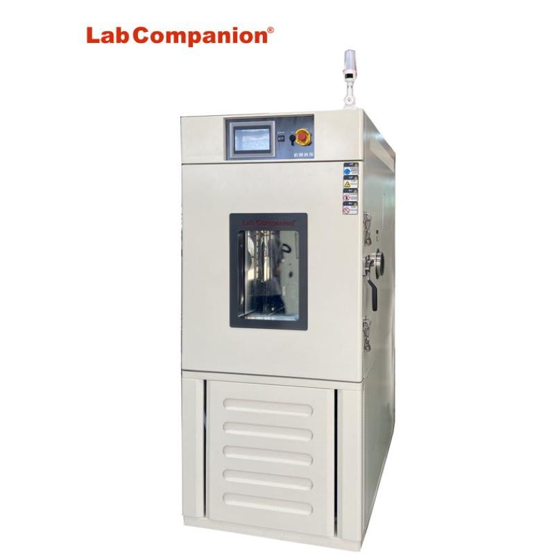
Vacuum High Temperature Test Chamber
Features of vacuum high temperature test chamber: special high temperature equipment for defoaming and anti-oxidation. And it meets the standards: GB/T2423.1 (IEC60068-2-1), GB/T2423.2 (IEC60068-2-2), ISO16750; JESD22, GB/T 14710, GB/T 13543.
First, product overview of vacuum high temperature test chamber:
New and simple design;
The program of automatic control of pressure and temperature control is easy to operate and advanced in function;
Observation window for easy observation of test material status (optional);
Dual structure in the chamber: the inside of the vacuum container has a dual structure of an inner slot, and a heater is set outside the inner chamber to reduce heat loss, improve temperature uniformity, greatly shorten the temperature rising time, and improve the operating rate of the equipment;
Widely used: can be used for defoaming, degassing, hardening, drying and so on;
Resin liquid mixing and silicone liquid when the defoaming treatment in LED production process, various resin molding degas treatment, IC injection of epoxy resin hardening treatment, drying for electronic parts after water cleaning, vacuum high temperature test chamber can be used in all these process;
Second, different models of vacuum high temperature test chamber:
Model number
Temperature range
Internal volume
Type
Internal size
(W*H*Dmm)
External size
(W*H*Dmm)
VAC-101P
+40~+200℃
91L
Atmospheric pressure range:933~1[*102Pa](abs)
450×450×450
902×1,392×780
VAC-201P
+40~+200℃
216L
Atmospheric pressure range:933~1[*102Pa](abs)
600×600×600
1,052×1,532×930
VAC-301P
+40~+200℃
512L
Atmospheric pressure range:933~1[*102Pa](abs)
800×800×800
1,252×1,772×1,130
Model number
Temperature/pressure range
Internal size
(W*H*Dmm)
LCV-234
(RT+20)°C~+200°C / 0-101kPa(Gauge)
450×450×450
LCV-244
550×550×550
Environmental Test Solutions For Mechanical And Electrical Products
The statistical analysis shows that the failure of electronic components accounts for 50% of the failure of electronic complete machine, and the reliability detection technology still faces many challenges.
Industry
Test object
Use
Technology
Solution
Electromechanical
System component
Evaluate
Thermal cycling test
High and low temperature (&humidity) test chamber
Thermal cycling test
Rapid temperature (&humidity)change test chamber
Electric gas
Evaluate
Thermal cycling test
High and low temperature (&humidity) test chamber
Thermal cycling test
Rapid temperature (&humidity)change test chamber
Railway traffic
Evaluate
Thermal cycling test
High and low temperature (&humidity) test chamber
Thermal cycling test
Rapid temperature (&humidity)change test chamber
/
High and low temperature (&humidity) test chamber
/
Small ultra-low temperature test chamber
Environmental test Solutions for Vehicle Transport Auto Parts
The reliability of vehicle transportation auto parts products is very important, which directly determines the safety, reliability and operation comfort of the vehicle.
Industry
Test object
Use
Technology
Solution
Automobile industry
Automotive electronics
Inspect
High and low temperature test
High and low temperature (&humidity) test chamber
Evaluate
High and low temperature test
High temperature test chamber
Condensation power test
Rapid temperature (&humidity)change test chamber
Characteristic test
Rapid temperature (&humidity)change test chamber
Car battery
Inspect
Charge and discharge test
High and low temperature (&humidity) test chamber
Evaluate
Characteristic test
Rapid temperature (&humidity)change test chamber
Walking safety device
Inspect
Aging of the substrate
High and low temperature (&humidity) test chamber
Evaluate
Characteristic test
High temperature test chamber
Occupant protection (air bag)
Inspect
Finished product screening
Rapid temperature (&humidity)change test chamber
Car driving guidance system
Inspect
Finished product screening
High and low temperature (&humidity) test chamber
Rapid temperature (&humidity)change test chamber
ETC vehicle operation system
Inspect
High and low temperature test
High and low temperature (&humidity) test chamber
High temperature test chamber
Evaluate
Characteristic test
Rapid temperature (&humidity)change test chamber
Other automotive associations (power semiconductors)
Place at high temperature
High temperature test chamber
High and Low Temperature Low Pressure Test Equipment & Rapid Decompression Device
High and low temperature low pressure test chamber:
(1). Main technical indicators
1. Studio size: 1000D×1000W×1000H mm, the internal size is about 1000L
2. External size: about 3400D×1400W×2010H mm, excluding the controller, test hole and other prominent parts.
3. Temperature range: -70℃ ~ +150℃
4. Temperature fluctuation: ≤±0.5℃, normal pressure, no load
5. Temperature deviation: ±2℃, normal pressure, no load
6. Temperature uniformity: ≤2℃, atmospheric pressure, no-load
7. Heating rate: +20℃→+150℃≤60min
8. Cooling rate: +20℃→-65℃≤60min
9. Humidity range: Humidity 20% ~ 98%RH (temperature +20℃ ~ +85℃ range)
10. Humidity deviation: ≤+ 2-3%RH (> 75%RH), ≤±5%RH(≤75%RH), under normal pressure and no-load conditions.
11. Pressure range: normal pressure ~ 0.5kPa
12. Pressure reduction rate: normal pressure ~ 1.0kPa≤30min
13. Pressure recovery rate: ≤10.0kPa/min
14. Pressure deviation: normal pressure ~ 40kPa:≤±2kPa, 40KPa ~ 4kPa:≤±5%kPa, below 4kPa:≤± 0.1kPa
15. Wind speed: frequency conversion adjustment
16. Power: about 50kW
17. Noise: ≤75dB (A), 1 meter away from the front of the chamber and 1.2 meters above the ground.
18. Weight: 1900Kg
(2). Rapid decompression device (optional)
In order to meet the requirements of rapid depressurization, an independent rapid depressurization chamber is processed. The rapid depressurization chamber is composed of a shell assembly, a pressure assembly, a door assembly, an interface and a moving frame. Before rapid decompression, the user needs to connect an external pipeline.
1. Studio size: 400mm deep x 500mm wide x 600mm long; The internal wall material is processed with 3.0 SUS304/2B, and 5mm square pipe is used as the pressure reinforcement.
2. External dimension: 530mm deep ×700mm wide ×880mm long, the external wall material is made of 1.2mm cold-rolled steel plate, the surface is sprayed white (consistent with the color of the chamber);
3. A pressure sensor port is reserved at the top of the container. The control sensor port is located at the rear of the container to facilitate the quick buck device to be routed.
4. For the convenience of moving fast buck device. Install four lifting casters under the frame; The moving frame is welded by ordinary steel and sprayed on the surface.
5. Rapid decompression process: In order to improve the pumping speed of rapid depressurization chamber, the test chamber is first pumped to about 1kPa, and the electric valve connecting the test chamber equipment and the fast reducing device is opened to realize the fast reducing function, and the valve is closed when it reaches 18.8kPa. The constant pressure in the fast relief chamber can be achieved by auxiliary pumping (intake valve).
(3). Product implementation standards
1. GB/T2423.1-2008 Test A: Low temperature test
2. GB/T2423.2-2008 Test B: Low temperature test
3. GB/T 2423.3-2006 test Cab: constant temperature and humidity test
4. GB/T 2423.4-2008 test Db: alternating temperature and humidity test
5. GB/T2423.21-2008 Test M: Low pressure test method
6. GB/T2423.25-2008 test Z/AM: Low temperature/low pressure comprehensive test
7. GB/T2423.26-2008 Test Z/BM: high temperature/low pressure comprehensive test
8. General requirements for GJB150.1-2009
9. GJB150.2A-2009 Low pressure (altitude) test
10. GJB150.3A-2009 high temperature test
11. GJB150.4A-2009 low temperature test
12. GJB150.6-86 temperature-height test
13. GJB150.19-86 Temperature - humidity - height test
14. DO16F rapid decompression test
15. GB/T 10586-2006 temperature and humidity test chamber technical conditions
16. GB/T 10590-2006 high temperature low pressure test chamber technical conditions
17. GB/T 10592-2008 high and low temperature test chamber technical standard
18. GB/T 5170.1-2008 General Rules for inspection methods of environmental test equipment for electrical and electronic industry
19. GB/T 5170.2-2008 Electrical and electronic products environmental test equipment test method temperature and humidity test equipment
20. GB/T 5170.5-2008 Electrical and electronic products environmental test equipment test method temperature and humidity test equipment
GB/T 5170.10-2008 Electrical and electronic products environmental test equipment test method high temperature low pressure test equipment
Vibrational Verification for Functionality(VVF)
In the vibration generated during transportation, freight boxes are susceptible to complex dynamic pressures, and the resonant response generated is violent, which may cause packaging or product failure. Identifying the critical frequency and the type of pressure on the package will minimize this failure. Vibration testing is the assessment of the vibration resistance of components, components and complete machines in the expected transport, installation and use environment.
Common vibration modes can be divided into sinusoidal vibration and random vibration. Sinusoidal vibration is a test method often used in the laboratory, which mainly simulates the vibration generated by rotation, pulsation and oscillation, as well as the resonance frequency analysis and resonance point residence verification of the product structure. It is divided into sweep frequency vibration and fixed frequency vibration, and its severity depends on the frequency range, amplitude value and test duration. Random vibration is used to simulate the overall structural seismic strength assessment of the product and the shipping environment in the packaged state, with the severity depending on the frequency range, GRMS, test duration and axial orientation.
Vibration can not only loosen the lamp components, so that the internal relative displacement, resulting in de-welding, poor contact, poor working performance, but also make the components produce noise, wear, physical failure and even component fatigue.
To this end, Lab Companion launched a professional "LED lamp vibration test" business to simulate the vibration or mechanical shock that may occur in the actual transportation, installation and use environment of the lamp, evaluate the vibration resistance of the LED lamp and the stability of its related performance indicators, and find the weak link that may cause damage or failure. Improve the overall reliability of LED products and improve the failure status of the industry due to transportation or other mechanical shocks.
Service customers: LED lighting factory, lighting agents, lighting dealers, decoration companies
Test method:
1, the LED lamp sample packaging placed on the vibration test bench;
2, the vibration speed of the vibration tester is set to 300 RPM, the amplitude is set to 2.54 cm, start the vibration meter;
3, the lamp according to the above method in the upper and lower, left and right, front and back three directions respectively test for 30 minutes.
Results evaluation: After the vibration test, the lamp can not occur parts falling off, structural damage, lighting and other abnormal phenomena.
Double 85 Constant Temperature And Humidity Reliability Environmental Test (THB)
First, high temperature and humidity test
WHTOL (Wet High Temperature Operating Life) is a common environmental stress acceleration test, usually 85℃ and 85% relative humidity, which is generally carried out in accordance with the standard IEC 60068-2-67-2019. The test conditions are shown in the chart.
Second, the test principle
"Double 85 test" is one of the reliability environmental tests, mainly used for constant temperature and humidity box, that is, the temperature of the box is set to 85℃, the relative humidity is set to 85%RH conditions, to accelerate the aging of the test product. Although the test process is simple, the test is an important method to evaluate many characteristics of the test product, so it has become an indispensable reliability environmental test condition in various industries.
After aging the product under the condition of 85℃/85%RH, compare the performance changes of the product before and after aging, such as the photoelectric performance parameters of the lamp, the mechanical properties of the material, yellow index, etc., the smaller the difference, the better, so as to test the heat and moisture resistance of the product.
The product may have thermal failure when working in a continuous high temperature environment, and some moisture sensitive devices will fail in a high humidity environment. The dual 85 test can test the thermal stress generated by the product under high humidity and its ability to resist long-term moisture penetration. For example, the frequent failure of various products in the humid weather period in the south is mainly due to the poor temperature and humidity resistance of the products.
3. Experimental factors
In the LED lighting industry, many manufacturers have used the double 85 test results as an important means to judge the quality of lamps. Various possible reasons why LED lamps fail the dual 85 test are:
1. Lamp power supply: poor heat resistance of shell, danger of short circuit in circuit, failure of protection mechanism, etc.
2. Lamp structure: unreasonable design of heat dissipation body, installation problems, materials are not resistant to high temperature.
3. Lamp light source: poor moisture resistance, packaging adhesive aging, high temperature resistance.
If you encounter a special use environment, such as the working environment temperature is severe, you need to test its high and low temperature resistance, the test method can refer to the high and low temperature test project.
4. Serve customers
01. Customer group
LED lighting factory, LED power plant, LED packaging factory
02. Means of detection
Constant temperature and humidity test chamber
03. Reference standards
Constant temperature and humidity tests for electrical and electronic products -- Environmental testing -- Part 2: Test methods -- Test Cab: Constant temperature and humidity test GB/T 2423.3-2006.
04. Service content
4.1 Refer to the standard, conduct double 85 test on the product, and provide the third party's test results report.
4.2 Provide the analysis and improvement plan of the product through the double 85 test.
High Temperature Furnace Inspection Index
What is the high temperature furnace test standard? What metrics are tested? How long is the detection cycle? Which items are tested?
Test items (reference) :
Temperature uniformity test, system accuracy test, temperature, system accuracy, temperature uniformity, high temperature furnace verification and calibration, high temperature furnace (tube furnace) verification and calibration, box resistance furnace (high temperature furnace, heat treatment furnace) verification and calibration, high temperature furnace (box resistance furnace, dry furnace, heat treatment furnace) verification and calibration, silica
List of testing standards:
1, NCS/ CJ M61; SAE AMS 2750; JJF1376 High temperature furnace calibration specification NCS/ CJ M61, high temperature furnace calibration method SAE AMS 2750E, box type resistance furnace calibration specification JJF1376
2, AMS 2750F High temperature measurement AMS 2750F
3, GB 25576-2010 Food safety national standard Food additive silica (high temperature furnace method)
4, JJF 1184 thermocouple verification furnace temperature field test technical specification
5, AMS 2750E high temperature measurement AMS 2750E
6, AMS 2750F high temperature determination method 3.5
7, AMS 2750G high temperature measurement AMS 2750G
8, AMS 2750E high temperature determination method 1
9. JJF 1376; AMS 2750; JJG 276 Calibration specification for box type resistance furnace JJF 1376, high temperature measurement method AMS 2750E, high temperature creep, durable strength testing machine verification regulation JJG 276
10, JJF 1376 box type resistance furnace calibration specification
11, GB/T 9452-2012 heat treatment furnace effective heating zone determination method 1
12. SAE AMS 2750 high-temperature calibration method F
Reliability Testing Acceleration Testing
Most semiconductor devices have lifetimes that extend over many years at normal use. However, we cannot wait years to study a device; we have to increase the applied stress. Applied stresses enhance or accelerate potential fail mechanisms, help identify the root cause, and help labcompanion take actions to prevent the failure mode.
In semiconductor devices, some common accelerants are temperature, humidity, voltage, and current. In most cases, the accelerated testing does not change the physics of the failure, but it does shift the time for observation. The shift between accelerated and use condition is known as ‘derating.’
Highly accelerated testing is a key part of JEDEC based qualification tests. The tests below reflect highly accelerated conditions based on JEDEC spec JESD47. If the product passes these tests, the devices are acceptable for most use cases.
Temperature Cycle
Per the JESD22-A104 standard, temperature cycling (TC) subjects the units to extreme high and low temperatures transitions between the two. The test is performed by cycling the unit's exposure to these conditions for a predetermined number of cycles.
High Temperature Operating Life (HTOL)
HTOL is used to determine the reliability of a device at high temperature while under operating conditions. The test is usually run over an extended period of time according to the JESD22-A108 standard.
Temperature Humidity Bias/Biased Highly Accelerated Stress Test (BHAST)
According to the JESD22-A110 standard, THB and BHAST subject a device to high temperature and high humidity conditions while under a voltage bias with the goal of accelerating corrosion within the device. THB and BHAST serve the same purpose, but BHAST conditions and testing procedures enable the reliability team to test much faster than THB.
Autoclave/Unbiased HAST
Autoclave and Unbiased HAST determine the reliability of a device under high temperature and high humidity conditions. Like THB and BHAST, it is performed to accelerate corrosion. Unlike those tests, however, the units are not stressed under a bias.
High Temperature Storage
HTS (also called Bake or HTSL) serves to determine long-term reliability of a device under high temperatures. Unlike HTOL, the device is not under operating conditions for the duration of the test.
Electrostatic Discharge (ESD)
Static charge is an unbalanced electrical charge at rest. Typically, it is created by insulator surfaces rubbing together or pulling apart; one surface gains electrons, while the other surface loses electrons. The result is an unbalanced electrical condition known as static charge.
When a static charge moves from one surface to another, it becomes Electrostatic Discharge (ESD) and moves between the two surfaces in a form of a miniature lightning bolt.
When a static charge moves, it becomes a current that can damage or destroy gate oxide, metal layers, and junctions.
JEDEC tests ESD in two different ways:
1. Human Body Mode (HBM)
A component level stress developed to simulate the action of a human body discharging accumulated static charge through a device to ground.
2. Charged Device Model (CDM)
A component level stress that simulates charging and discharging events that occur in production equipment and processes, per the JEDEC JESD22-C101 specification.
Conversion Between Accelerated Aging of Xenon Lamp Aging Test Chamber And Outdoor Aging
Generally speaking, it is difficult to have a detailed positioning and conversion formula for the conversion between accelerated aging of xenon lamp aging test chamber and outdoor aging. The biggest problem is the variability and complexity of the outdoor environment. The variables that determine the relationship between xenon lamp aging test chamber exposure and outdoor exposure include:
1. Geographical latitude of outdoor aging exposure sites (closer to the equator means more UV).
2. Altitude (Higher altitude means more UV).
3. Local geographical characteristics, such as the wind can dry the test sample or close to water will produce condensation.
4. Random changes in climate from year to year can lead to a 2:1 change in aging at the same location.
5. Seasonal changes (e.g., winter exposure may be 1/7 of summer exposure).
6. Direction of the sample (5° south vs. vertical facing north)
7. Sample insulation (outdoor samples with insulated backing age 50% faster than uninsulated samples).
8. Working cycle of xenon lamp aging box (light time and wet time).
9. The working temperature of the test chamber (the higher the temperature, the faster the aging).
10. Test the uniqueness of the sample.
11. Spectral Intensity Distribution (SPD) of laboratory light sources
Objectively speaking, accelerated aging and outdoor aging have no convertibility, one is a variable, one is a fixed value, the only thing to do is to obtain a relative value, rather than an absolute value. Of course, it is not to say that relative values have no effect; on the contrary, relative values can also be very effective. For example, you will find that a slight change in design may double the durability of standard materials. Or you may find the same looking material from multiple suppliers, some of which age quickly, most of which take a moderate amount of time to age, and a smaller amount that ages after longer exposure. Or you may find that less expensive designs have the same durability against standard materials that have satisfactory performance over actual service life, such as 5 years.
How Long Is the Xenon Lamp Weathering Test Chamber Equivalent to a Year of Outdoor Exposure?
How long is the xenon lamp weathering test chamber equivalent to a year of outdoor exposure? How to test out its durability? This is a technical problem, but also a lot of users are concerned about the problem. Today's engineers of Lab Companion are going to explain this problem.
This problem looks very simple, in fact, it is a complex problem.We can not just get a simple number, let this number and the test time of the xenon lamp weathering test chamber to multiply, so as to get the outdoor exposure time, nor is the quality of our xenon lamp weathering test chamber not good enough! No matter how good the quality of the xenon lamp weathering test chamber is, how advanced it is, it is still impossible to find only a number to solve the problem. The most important thing is that the outdoor exposure environment is complex and changeable, affected by many factors, what are the specific?
1. The influence of geographical latitude
2. The influence of altitude
3. The influence of geographical environment when testing, such as wind speed.
4. The impact of the season, winter and summer will be different, summer exposure is 7 times the damage of winter exposure.
5. Direction of the test sample
6. Is the sample insulated or uninsulated? Samples placed on insulators will generally age much faster than those not placed on insulators.
7. Test cycle of xenon lamp weathering test chamber
8. Xenon lamp weathering test chamber operating temperature, the higher the temperature, the faster the aging
9. Testing of special materials
10. Spectrum distribution in the laboratory


 Get A Quote


 IPv6 network supported