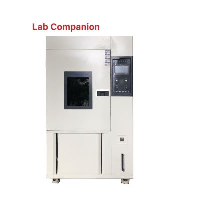
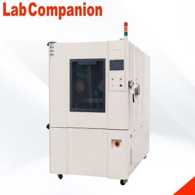
Specification for Ground Solar Radiation Simulation Test
The purpose of this test method is to determine the physical and chemical effects of components and equipment exposed to solar radiation on the Earth surface (e.g. The main characteristics of the simulated environment in this experiment are the solar spectral energy distribution and intensity of received energy under the control of temperature and humidity in the test environment. There are three procedures in the test mode (Procedure A: thermal effect evaluation, procedure B: degradation effect evaluation, procedure C: photochemical effect evaluation).
Applicable products:
Electronic products that will be used outside the home for a long time, such as: laptops, mobile phones, MP3&MP4, GPS, automotive electronics, digital cameras, PDAs, low-cost laptops, easy to carry laptops, video cameras, Bluebud headphones
Test requirements:
1. Spectral energy distribution shall meet the requirements of the specification
2. Illuminance: 1.120KW/m^2 (±10%)=[300-400um, 63 w/m2][The total global radiation of the earth's surface from the sun and the sky vertical is 1.120KW/m^2]
3. Temperature and humidity 40℃(±2)/93%(±3)R.H.
4. This test needs to control the humidity environment
5. During irradiation, the temperature in the box rises to the specified temperature (40℃, 55℃) at a linear rate.
6. The temperature in the box should start to rise 2 hours before irradiation
7. The temperature in the dark chamber should be decreased linearly and maintained at 25℃
8. Temperature error: ±2℃
9. The temperature measurement point in the box is taken from the test distance of 1m from the specimen or half of the box wall distance (the smaller one)
Spectral energy distribution and tolerance error range of Xenon lamp (according to the requirements of the International Illuminance Commission CIE)
The xenon lamp weather testing machine is not lit, but the spectrum output by its xenon lamp must be output in accordance with the requirements of the International Illuminance Commission CIE. Therefore, the equipment manufacturer of the weather testing machine must have the equipment (spectrometer) and technical capability to verify the xenon lamp spectrum (provide xenon lamp verification report).
Test procedure evaluation description:
According to IEC68-2-5&IEC-68-2-9, there are three kinds of test methods for light resistance test, which can be divided into program A: thermal effect, B: degradation effect, C: photochemistry. Among these three methods, procedure A is the most severe test method, which will be detailed in the following article.
Three test procedures: Procedure A: thermal effect (most severe natural conditions), B: degradation effect (22.4KWh/m2 per day), C: photochemistry
Program A: Thermal effect
Test conditions: 8 hours of exposure, 16 hours of darkness, a total of 24 hours per cycle, three cycles were required, and the total exposure of each cycle was 8.96KWh/m2
Procedure A test precautions:
Instructions: In the test process of program A, the xenon lamp is not lit immediately at the beginning of the test, according to the requirements of the code, it must be lit after 2 hours of the test, closed at 10 hours, and the total irradiation time of a cycle is 8 hours. During the lighting process, the temperature in the furnace rises linearly from 25℃ to 40℃(satisfying most environments in the world) or 55℃(satisfying all environments in the world), and decreases linearly at 10 hours to 25℃ for 4 hours, with a linear slope (RAMP) of 10 hours.
Test procedure B: Degradation effect
Test conditions: Temperature and humidity in the first four hours of the test was (93%), irradiation for 20 hours, darkness for 4 hours, a total of 24 hours per cycle Total exposure for each cycle was 22.4KWh/m2 cycles: 3(3 days: commonly used), 10(10 days), 56(56 days)
Procedure B test precautions:
Instructions: Procedure B test is the only test condition for humidity control during light resistance test in IEC68-2-5 specification. The specification requires that the temperature and humidity conditions are (40±2℃/93±3%) within four hours from the beginning of the test [supplementary description in IEC68-2-9] humidity environment, which should be paid attention to when conducting the test. At the beginning of the program B test, the temperature was raised from 25℃ linear slope (RAMP: 2 hours) to 40℃ or 55℃, maintained for 18 hours, and then the linear cooling (RAMP: 2 hours) returned to 25℃ for 2 hours to complete a cycle of experiments. Remarks: IEC68-2-9 = Solar Radiation Test Guidelines
Test procedure C: Photochemistry (Continuous Irradiation)
Test conditions: 40℃ or 55℃, continuous irradiation (depending on the time required)
Procedure C test precautions:
Note: After the linear temperature rise (RAMP: 2 hours) from 25℃ to 40℃ or 55℃, the continuous irradiation test was carried out at a fixed temperature before the end of the test. The irradiation time was determined according to the characteristics of the product to be tested in the test, which was not clearly specified in the specification.
Bellcore GR78-CORE Test Specification
Bellcore GR78-CORE is one of the specifications used in the early surface insulation resistance measurement (such as IPC-650). The relevant precautions in this test are organized for the reference of the personnel who need to carry out this test, and can also provide a preliminary understanding of this specification.
Test purpose:
Surface Insulation resistance testing
1. Constant temperature and humidity test chamber: the minimum test conditions are 35°C±2°C/85%R.H, 85 ±2°C/85%R.H.
2. Ion migration measurement system: Allowing the insulation resistance of the test circuit (pattern) to be measured under these conditions, a power supply will be able to provide 10 Vdc / 100μA.
Test procedure:
a. The object to be measured is tested after 24 hours at 23℃(73.4℉)/50%R.H. condition.
b. Place limited Test patterns on an appropriate rack and keep the test circuits at least 0.5 inches apart, keep air flow and the rack in the furnace until the end of the experiment.
c. Place the shelf in the center of the constant temperature and humidity machine, align and parallel the test board with the air flow in the chamber, and lead the line to the outside of the chamber, so that the wiring is far away from the test circuit.
d. Close the furnace door and set the condition to 35 ±2°C, at least 85%R.H. and allow the furnace to spend several hours stabilizing
e. After 4 days, the insulation resistance will be measured and the measured value will be recorded periodically between 1 and 2,2 and 3,3 and 4, 4 and 5 using an applied voltage of 45 ~ 100 Vdc. Under the test conditions, the test is sent out the measured voltage to the circuit after 1 minute. 2 and 4 are periodically at an identical potential. And 5 periodically at opposite potentials.
f. This condition only applies to transparent or translucent materials, such as solder masks and conformal coatings.
g. As for multilayer printed circuit boards required for insulation resistance testing, the only normal procedure will be used for insulation resistance testing circuit products. Extra cleaning procedures are prohibited.
Method of conformity determination:
1. After the electron migration test is completed, the test sample is removed from the test furnace, illuminated from the back and tested at 10 x magnification, and will not be found to reduce the electron migration (filamental growth) phenomenon by more than 20% between the conductors.
2. adhesives will not be used as a basis for republication when determining compliance with the 2.6.11 test method of IPC-TM-650[8] to examine appearance and surface item by item.
Reasons why insulation resistance does not meet the requirements:
1. Contaminants weld the cells like wires on the insulating surface of the substrate, or are dropped by the water of the test furnace (chamber)
2. Incompletely etched patterns will reduce the insulation distance between conductors by more than permitted design requirements
3. Chafes, breaks, or significantly damages the insulation between conductors


 Get A Quote


 IPv6 network supported