In environmental reliability testing, high-low temperature humidity test chambers and constant temperature and humidity test chambers are easily confused due to similar names, but they differ significantly in testing capabilities, applications and technical characteristics. Accurate distinction and selection are key to ensuring valid test data. This blog will analyze the core differences and provide selection suggestions.
I. Core Definition: Essential Distinction of Functional Boundaries
The core difference between the two starts with functional positioning, which directly determines the applicable scenarios.
The core of the constant temperature and humidity test chamber is "maintaining stability". It can accurately control and maintain the set temperature and humidity for a long time, and is used to simulate the long-term performance of products in specific environments, such as electronic component stability testing and textile temperature-humidity sensitivity testing. Its core requirement is "steady-state environmental performance verification".
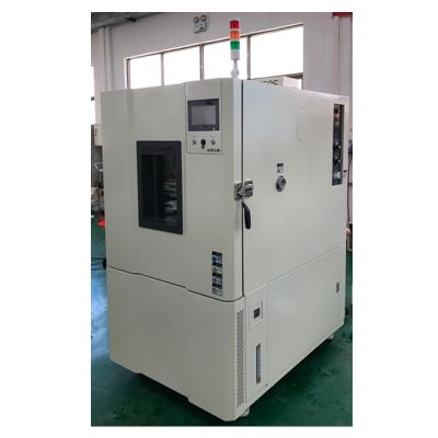
The high-low temperature humidity test chamber focuses on "dynamic simulation". In addition to precise temperature and humidity control, it has a wide-range fluctuation capability, which can simulate environments such as high-low temperature cycles and alternating humidity and heat, such as extreme temperature differences during product transportation and diurnal temperature-humidity changes of outdoor equipment. Its core requirement is "dynamic environmental reliability verification".
II. Key Differences: Multi-dimensional Analysis from Technology to Application
1. Temperature and Humidity Range and Fluctuation Capacity
The constant temperature and humidity chamber has a mild temperature and humidity range (temperature 0℃-100℃, humidity 30%-95%RH) and high control precision (temperature fluctuation ±0.5℃, humidity ±2%RH), but no extreme temperature-humidity impact capability.
The high-low temperature humidity chamber has a wider temperature and humidity coverage (temperature -70℃~200℃, humidity 10%-98%RH) and rapid change capability (heating rate 3℃/min-15℃/min, cooling rate 1℃/min-10℃/min), which can realize rapid cycle switching between "high temperature and high humidity - low temperature and low humidity"—a feature unavailable in the former.
2. Differences in Core Technical Architecture
The constant temperature and humidity chamber adopts single-stage compression refrigeration, conventional resistance heating, and steam or ultrasonic humidification. Its system design focuses on "energy saving and stability", with simple structure and low operating cost.
To meet extreme needs, the high-low temperature humidity chamber uses cascade refrigeration, rapid-heating tubes, and its humidity system includes a fast-response dehumidification module, with a thicker insulation layer on the chamber wall. Its technical complexity and manufacturing cost are much higher than the former.
3. Applicable Scenarios and Testing Purposes
The constant temperature and humidity chamber is used for steady-state environmental adaptability testing, such as electronic component aging and pharmaceutical storage simulation, to verify the performance consistency and durability of products in a fixed environment.
The high-low temperature humidity chamber focuses on dynamic reliability testing, such as high-low temperature cycling of auto parts and extreme environment simulation of aerospace products, to expose product defects (material aging, structural deformation, etc.) under drastic environmental changes.
In summary, the constant temperature and humidity chamber guards the steady-state environment, while the high-low temperature humidity chamber challenges the dynamic environment. There is no absolute advantage or disadvantage between the two. Only by matching needs, clarifying scenarios and budgets can the test truly guarantee product quality.
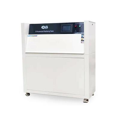
UV aging tester testing equipment
The structure of the test chamber is made of corrosion-resistant metal materials, including 8 fluorescent ultraviolet lamps, a water tray, a test sample holder, and temperature and time control systems and indicators.
2. The lamp power is 40W and the lamp length is 1200mm. The range of the uniform working area of the test box is 900 × 210mm.
3. The lights are installed in four rows, divided into two rows. The tubes of each row of lights are installed in parallel, and the center distance of the lights is 70mm.
4. The test sample is fixedly installed at a position 50mm away from the surface of the lamp surface. The test sample and its bracket form the inner wall of the box, and their backs are exposed to cooling air at room temperature due to the temperature difference between the test sample and the air inside the box. To create stable condensation conditions on the surface of the test sample during the condensation stage, the test chamber should generate natural air convection through the outer wall of the chamber and the channel of the test sample at the bottom.
5. Water vapor is generated by a water tray located at the bottom of the heating box, with a water depth not exceeding 25mm, and equipped with an automatic water supply controller. The water tray should be regularly cleaned to prevent the formation of scale.
6. The temperature of the test chamber is measured by a sensor fixed on a black aluminum plate (blackboard) with a width of 75mm, height of 100mm, and thickness of 2.5mm. The blackboard should be placed in the central area of the exposure test, and the measurement range of the thermometer is 30-80 ℃ with a tolerance of ± 1 ℃. The control of lighting and condensation stages should be carried out separately, and the condensation stage is controlled by the heating water temperature.
7. The test chamber should be placed in a test room with a temperature of 15-35 ℃, 300mm away from the wall, and should prevent the influence of other heat sources. The air in the test room should not circulate strongly to avoid affecting the lighting and condensation conditions.
Dear customer:
Hello, our company is a high-quality development team with strong technical strength, providing high-quality products, complete solutions, and excellent technical services to our customers. The main products include walk-in constant temperature and humidity testing chambers, UV accelerated aging testing machines, rapid temperature change testing chambers, walk-in environmental testing chambers, UV aging testers, constant temperature and humidity chambers, etc. Our company adheres to the principle of building a business with integrity, maintaining quality, and striving for progress. With a more determined pace, we continuously climb new heights and contribute to the national automation industry. We welcome new and old customers to confidently choose the products they like. We will serve you wholeheartedly!
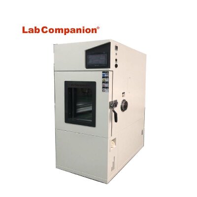
Structural characteristics of temperature and humidity control box
The full name of the temperature and humidity control chamber is "Constant Temperature and Humidity Test Chamber", which is an essential testing equipment in aviation, automotive, home appliances, scientific research and other fields. It is used to test and determine the parameters and performance of electrical, electronic and other products and materials after high temperature, low temperature, humidity and heat or constant temperature environment changes. It can be mainly divided into "desktop" and "vertical" according to testing requirements and standards, with the difference being the temperature and humidity that can be achieved. The vertical type can be used for low temperature and drying below room temperature, while the desktop type can only be used for temperature and high humidity above room temperature.
Suitable for various small electrical appliances, instruments, materials, and components for wet heat testing, it is also suitable for conducting aging tests. This test chamber adopts the most reasonable structure and stable and reliable control method currently available, making it aesthetically pleasing, easy to operate, safe, and with high precision in temperature and humidity control. It is an ideal equipment for conducting constant temperature and humidity tests.
1) The test box body is in the form of an integral structure, with the refrigeration system located at the lower rear of the box and the control system located at the upper part of the test box.
(2) Inside the air duct interlayer at one end of the studio, there are devices such as heaters, refrigeration evaporators, and fan blades distributed; On the left side of the test box, there is a Ø 50 cable hole, and the test box is a single door (stainless steel embedded door handle)
(3) The double-layer high temperature and anti-aging silicone rubber seal can effectively ensure the temperature loss of the test chamber
(4) There are observation windows, frost prevention devices, and switchable lighting fixtures on the box door. The observation window adopts multi-layer hollow tempered glass, and the inner adhesive sheet conductive film is heated and defrosted. The lighting fixtures use imported brand Philips lamps, which can effectively observe the experimental changes in the studio from all angles.
Dear customer:
Hello, our company is a high-quality development team with strong technical strength, providing high-quality products, complete solutions, and excellent technical services to our customers. The main products include walk-in constant temperature and humidity testing chambers, UV accelerated aging testing machines, rapid temperature change testing chambers, walk-in environmental testing chambers, UV aging testers, constant temperature and humidity chambers, etc. Our company adheres to the principle of building a business with integrity, maintaining quality, and striving for progress. With a more determined pace, we continuously climb new heights and contribute to the national automation industry. We welcome new and old customers to confidently choose the products they like. We will serve you wholeheartedly!
Temperature control of solar simulation irradiation test chamber
The test chamber uses an artificial light source combined with a G7 OUTDOOR filter to adjust the system light source to meet the requirements of IEC61646 for solar simulators by simulating the radiation in natural sunlight. The above system light source is used to conduct the IEC61646 photoaging test on the solar cell module, and the temperature on the back of the module needs to be constantly controlled between 50 ± 10℃during the test. Can automatically monitor temperature; Configure a radiometer to control the irradiance of light, ensuring it remains stable at a specified level, while also controlling the testing time.
During the ultraviolet light cycle period in the solar simulation irradiation test chamber, photochemical reactions are usually not sensitive to temperature. But the rate of any subsequent reaction depends on the temperature. The rate of these reactions accelerates with increasing temperature. Therefore, controlling the temperature during UV exposure is crucial. In addition, it is necessary to ensure that the temperature of the accelerated aging test is consistent with the highest temperature at which the material is directly exposed to sunlight. In the solar simulation irradiation test chamber, the UV exposure temperature can be set at any temperature between 50 ℃ and 80 ℃ based on the illuminance and ambient temperature. The UV exposure temperature is adjusted by a sensitive temperature controller and blower system to achieve excellent uniformity in the temperature of this test chamber.
Dear customer:
Hello, our company is a high-quality development team with strong technical strength, providing high-quality products, complete solutions, and excellent technical services to our customers. The main products include walk-in constant temperature and humidity testing chambers, UV accelerated aging testing machines, rapid temperature change testing chambers, walk-in environmental testing chambers, UV aging testers, constant temperature and humidity chambers, etc. Our company adheres to the principle of building a business with integrity, maintaining quality, and striving for progress. With a more determined pace, we continuously climb new heights and contribute to the national automation industry. We welcome new and old customers to confidently choose the products they like. We will serve you wholeheartedly!
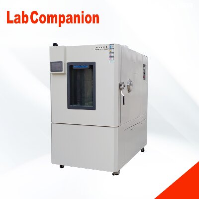
Factors causing uneven temperature inside the high and low temperature humid heat test chamber
The high and low temperature damp heat test chamber is the main equipment in temperature and humidity environment testing, mainly used for conducting high and low temperature and humidity tests to evaluate the temperature and humidity resistance of products, so as to ensure that our products can work and operate normally under any environmental conditions. However, if the temperature uniformity exceeds the allowable deviation range during environmental testing in the high and low temperature damp heat test chamber, the data obtained from the test is unreliable and cannot be used as the ultimate tolerance for high and low temperature testing of materials or products. So what are the reasons that can cause temperature uniformity to exceed the allowable deviation range?
1. The differences in the test objects in the high and low temperature humid heat test chamber: If enough test samples that affect the overall internal heat convection are placed in the high and low temperature test chamber, it will inevitably affect the uniformity of the internal temperature to a certain extent, that is, the temperature uniformity. For example, if LED lighting products are placed, the products themselves emit light and heat, becoming a thermal load, which has a significant impact on temperature uniformity.
2. The design issues make it difficult to achieve a uniform symmetrical structure in the internal structure and space of the high and low temperature wet heat test chamber, and an asymmetric structure will inevitably lead to deviations in the uniformity of internal temperature. This aspect is mainly reflected in sheet metal design and processing, such as the design of air ducts, the placement of heating pipes, and the size of fan power. All of these will affect the temperature uniformity inside the box.
3. Due to the different structures of the inner wall of the high and low temperature humid heat test chamber, the temperature of the inner wall of the test chamber will also be uneven, which will affect the heat convection inside the working chamber and cause deviation in the internal temperature uniformity.
4. Due to the different heat transfer coefficients on the front, back, left, right, top, and bottom surfaces of the box wall in the studio, some have threading holes, detection holes, testing holes, etc., which cause local heat dissipation and transfer, resulting in uneven temperature distribution of the box body and uneven radiative convective heat transfer on the box wall, affecting temperature uniformity.
5. The sealing of the box and door is not strict, for example, the sealing strip is not customized and has seams, and the door leaks air, which affects the temperature uniformity of the workspace.
6. If the volume of the test object is too large, or if the position or method of placing the test object in the high and low temperature damp heat test chamber is inappropriate, it will obstruct the air convection inside and also cause significant temperature uniformity deviation. Placing the test product next to the air duct seriously affects the circulation of air, and of course, the uniformity of temperature will be greatly affected.
In summary, all of these points are the main culprits that affect the temperature uniformity inside the high and low temperature humid heat test chamber. We hope that everyone can investigate from these aspects one by one, which will surely solve your confusion and difficulties.
Dear customer:
Hello, our company is a high-quality development team with strong technical strength, providing high-quality products, complete solutions, and excellent technical services to our customers. The main products include walk-in constant temperature and humidity testing chambers, UV accelerated aging testing machines, rapid temperature change testing chambers, walk-in environmental testing chambers, UV aging testers, constant temperature and humidity chambers, etc. Our company adheres to the principle of building a business with integrity, maintaining quality, and striving for progress. With a more determined pace, we continuously climb new heights and contribute to the national automation industry. We welcome new and old customers to confidently choose the products they like. We will serve you wholeheartedly!
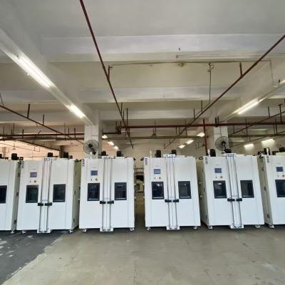
The development prospects of high and low temperature wet heat test chambers are promising
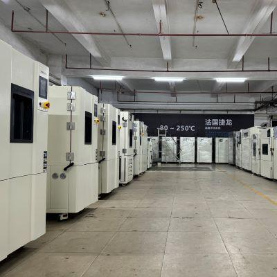
Nowadays, China's environmental testing equipment industry is rapidly developing, constantly innovating and surpassing. However, compared to the international level, China has only reached the technical level of the mid-1990s. The development of modern industrial testing equipment not only depends on the level of product technology, but also involves engineering application technology. But many products in our country have already reached the level of international mainstream products, with a wide variety, complete specifications, low prices, and are very competitive in the international market; For example, the high and low temperature wet heat test chamber has reached the international product level.
The high and low temperature damp heat test chamber in China has done very well both in terms of product reliability and product precision. Now the test chamber in China is becoming more and more intelligent and integrated into the Internet. As long as you have a computer, you can control it anywhere and anytime; And the price is relatively cheaper compared to foreign countries, with the same quality but different prices. However, it is still necessary to constantly innovate technological indicators, constantly surpass oneself, and become a leader in environmental testing equipment. From the current perspective, the development path of high and low temperature wet heat test chambers is bright.
On the other hand, China's environmental testing equipment industry is accelerating from laboratories to the forefront of production, and to people's homes and lives. Portable, handheld, and personalized instruments are developing in large numbers, and commodity testing, environmental testing, and health testing have become new demand hotspots; The current trend in the development of instruments and meters is on the rise. It is believed that soon, China's leading product in the environmental testing industry, the high and low temperature wet heat test chamber, will be far ahead in terms of technology, brand, and other aspects internationally.
Dear customer:
Hello, our company is a high-quality development team with strong technical strength, providing high-quality products, complete solutions, and excellent technical services to our customers. The main products include walk-in constant temperature and humidity testing chambers, UV accelerated aging testing machines, rapid temperature change testing chambers, walk-in environmental testing chambers, UV aging testers, constant temperature and humidity chambers, etc. Our company adheres to the principle of building a business with integrity, maintaining quality, and striving for progress. With a more determined pace, we continuously climb new heights and contribute to the national automation industry. We welcome new and old customers to confidently choose the products they like. We will serve you wholeheartedly!
Basic troubleshooting methods for high and low temperature test chambers:
1、 High and low temperature testing equipment. In high temperature testing, if the temperature change does not reach the test temperature value, the electrical system can be checked and the faults can be eliminated one by one. If the temperature rises slowly, you need to check the air circulation system to see if the regulating baffle of the air circulation is open normally. Otherwise, check the motor of the air circulation
Is the operation normal. If the temperature overshoot is severe, it is necessary to adjust the PID setting parameters. If the temperature rises directly and is protected against overheating, the controller will malfunction and the control instrument must be replaced.
2、 When the high and low temperature test equipment suddenly malfunctions during the test operation, the corresponding fault display prompt and audible alarm prompt will appear on the control instrument. The operator can quickly identify which type of fault it belongs to by referring to the troubleshooting chapter in the operation and use of the equipment, and then ask professional personnel to quickly troubleshoot it to ensure the normal progress of the experiment. Other environmental testing equipment may experience other phenomena during use, so it is necessary to analyze and eliminate them specifically. Regular maintenance and upkeep of environmental testing equipment, regular cleaning of the condenser in the refrigeration system, lubrication of moving parts according to the instructions, and regular maintenance and inspection of the electrical control system are essential tasks
3、 If the low temperature of the high and low temperature testing instrument cannot meet the test indicators, then you need to observe the temperature changes, whether the temperature drops very slowly or there is a trend of temperature recovery after reaching a certain value. The former needs to check whether the working chamber is dried before conducting the low temperature test, so that the working chamber can be kept dry before putting the test sample into the working chamber for further testing. If there are too many test samples placed in the working chamber, which prevent the air in the working chamber from fully circulating, after ruling out the above reasons, you need to consider whether it is a fault in the refrigeration system. In this case, you need to hire professional personnel from the Lab Companion manufacturer for maintenance. The latter phenomenon is caused by poor usage environment of the equipment. The temperature and location of the equipment placement (distance between the box and the wall) must meet the requirements (as specified in the equipment operation instructions).
At present, the company's main products include: high and low temperature test chambers, rapid temperature change test chambers, constant temperature and humidity test chambers, and high and low temperature impact test chambers.
Service conditions for high, low temperature, and low pressure test chambers
One of the usage conditions for high, low temperature, and low pressure test chambers: environmental conditions
a、 Temperature: 15 ℃~35 ℃;
b、 Relative humidity: not exceeding 85%;
c、 Atmospheric pressure: 80kPa~106kPa
d、 There is no strong vibration or corrosive gas in the surrounding area;
e、 No direct sunlight exposure or direct radiation from other cold or heat sources;
f、 There is no strong airflow around, and when the surrounding air needs to be forced to flow, the airflow should not be directly blown onto the box;
g、 The influence of magnetic field on the control circuit of the interference free test box in the surrounding area;
h、 There is no high concentration of dust or corrosive substances in the surrounding area.
Condition 2 for the use of high, low temperature, and low pressure test chambers: Power supply conditions
a、 AC voltage: 220V ± 22V or 380V ± 38V;
b、 Frequency: 50HZ ± 0.5HZ
Condition Three for the Use of High, Low Temperature, and Low Pressure Test Chambers: Water Supply Conditions
It is advisable to use tap water or circulating water that meets the following conditions:
a、 Water temperature: not higher than 30 ℃;
b、 Water pressure: 0.1MPa~0.3MPa;
c、 Water quality: meets industrial water standards.
Condition 4 for the use of high, low temperature, and low pressure test chambers: Test load conditions
The load of the test chamber should meet the following conditions every week:
a、 The total mass of the load shall not exceed 80KG per cubic meter within the working chamber volume
b、 The total volume of the load shall not exceed 5/1 of the working chamber volume
c、 On any cross-section perpendicular to the prevailing wind direction, the sum of the load areas should not exceed 3/1 of the cross-sectional area of the working chamber at that location, and the load should not obstruct the flow of airflow when placed.
Dear customer:
Our company has products such as rapid temperature change test chambers, UV accelerated weather resistance testing machines, and temperature and humidity control chambers. You can call our service hotline through our website to learn more about our products. Our pursuit is endless, and we welcome new and old customers to choose their favorite products with confidence. We will be dedicated to serving you!
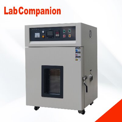
Precision Oven Manual
Precision ovens are suitable for semiconductor devices in the electronic industry, curing and aging of electronic components, high-temperature precision testing of plastic and rubber, molding processes for telephone handle wires, as well as experimental or workshop production lines in higher education research institutions and industrial and mining enterprises that require high product temperatures.
This instrument is equipped with a two-level temperature control system, dual protection, automatic cut-off for overheating, safe and reliable. The column alarm device has a temperature rise and constant temperature light display. When using this instrument in large quantities in the production workshop, which instrument has reached the constant temperature requirement and which one is still in the heating state can be clearly seen.
The instrument liner is made of high-quality mirror stainless steel, the outer shell is sprayed with plastic, and a safety door lock is installed. The front door adopts a high-temperature resistant glass observation window, which can observe the condition of the test piece inside the box at any time.
Dear customer:
Our company has products such as rapid temperature change test chambers, UV accelerated weather resistance testing machines, and temperature and humidity control chambers. You can call our service hotline through our website to learn more about our products. Our pursuit is endless, and we welcome new and old customers to choose their favorite products with confidence. We will be dedicated to serving you!
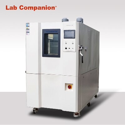
A Brief Analysis of the Five Characteristics of Walk in Laboratories
The walk-in laboratory has been upgraded on the basis of the original walk-in laboratory, with the characteristics of large testing space and operators being able to operate the test products in the laboratory, providing conditions for temperature and humidity environment testing for industrial manufacturers' batch or large parts, semi-finished products, and finished products. Adopting advanced Chinese LCD display screen touch screen, various complex program settings can be carried out. The program settings adopt dialogue mode, and the operation is simple and fast. It can achieve automatic operation of the refrigeration machine, maximizing automation, and can be equipped with LAN communication interfaces for users to remotely process and centrally control. It can record temperature and temperature parameters for 90 days, and is equipped with a paperless recorder.
5 characteristics of walk-in laboratory
1. Having an extremely wide temperature and humidity control range, it can meet various needs of users. By adopting a unique balanced temperature and humidity control method, a safe and precise temperature and humidity environment can be achieved. Having stable and balanced heating and humidification performance, it can achieve high-precision and highly stable temperature and humidity control.
2. Equipped with high-precision intelligent temperature regulators, temperature and humidity are displayed using LED digital display. Optional temperature and humidity recorder.
3. The refrigeration circuit is automatically selected, and the automatic control device has the performance of automatically selecting and operating the refrigeration circuit according to the set value of temperature, achieving direct start of the refrigeration machine and direct cooling under high temperature conditions.
4. The inner door is equipped with a large observation window, which facilitates the observation of the experimental status of the test samples.
5. Equipped with advanced safety and protection devices - residual current circuit breaker, over temperature protector, phase loss protector, and water cut-off protector.
Dear customer:
Our company has products such as rapid temperature change test chambers, UV accelerated weather resistance testing machines, and temperature and humidity control chambers. You can call our service hotline through our website to learn more about our products. Our pursuit is endless, and we welcome new and old customers to choose their favorite products with confidence. We will be dedicated to serving you!
User selection environment test box must read
1、 Equipment selection criteria
There is currently no exact number of natural environmental factors and induced environmental factors that exist on the surface of the Earth and in the atmosphere, among which there are no less than a dozen factors that have a significant impact on the use and lifespan of engineering products (equipment). Engineers engaged in the study of environmental conditions for engineering products have compiled and summarized the environmental conditions that exist in nature and are induced by human activities into a series of testing standards and specifications to guide the environmental and reliability testing of engineering products. For example, GJB150- the National Military Standard of the People's Republic of China for Environmental Testing of Military Equipment, and GB2423- the National Standard of the People's Republic of China for Environmental Testing of Electrical and Electronic Products, which guides environmental testing of electrical and electronic products. Therefore, the main basis for selecting environmental and reliability testing equipment is the testing specifications and standards of engineering products.
Secondly, in order to standardize the tolerance of environmental testing conditions in experimental equipment and ensure the control accuracy of environmental parameters, national technical supervision agencies and various industrial departments have also formulated a series of calibration regulations for environmental testing equipment and detection instruments. Such as the national standard GB5170 of the People's Republic of China "Basic Parameter Calibration Method for Environmental Testing Equipment of Electrical and Electronic Products", and JJG190-89 "Trial Calibration Regulations for Electric Vibration Test Stand System" issued and implemented by the State Administration of Technical Supervision. These verification regulations are also an important basis for selecting environmental and reliability testing equipment. Testing equipment that does not meet the requirements of these verification regulations is not allowed to be put into use.
2、 Basic principles for equipment selection
The selection of environmental and reliability testing equipment should follow the following five basic principles:
1. Reproducibility of environmental conditions
It is impossible to fully and accurately reproduce the environmental conditions that exist in nature in the laboratory. However, within a certain tolerance range, people can accurately and approximately simulate the external environmental conditions that engineering products undergo during use, storage, transportation, and other processes. This passage can be summarized in engineering language as follows: "The environmental conditions (including platform environment) created by the testing equipment around the tested product should meet the requirements of the environmental conditions and their tolerances specified in the product testing specifications. The temperature box used for military product testing should not only meet the requirements of the national military standards GJB150.3-86 and GJB150.4-86 for different uniformity and temperature control accuracy. Only in this way can the reproducibility of environmental conditions be ensured in environmental testing.
2. Repeatability of environmental conditions
An environmental testing equipment may be used for multiple tests of the same type of product, and a tested engineering product may also be tested in different environmental testing equipment. In order to ensure the comparability of test results obtained for the same product under the same environmental testing conditions specified in the testing specifications, it is necessary to require the environmental conditions provided by the environmental testing equipment to be reproducible. This means that the stress levels (such as thermal stress, vibration stress, electrical stress, etc.) applied by environmental testing equipment to the tested product are consistent with the requirements of the same testing specification.
The repeatability of environmental conditions provided by environmental testing equipment is guaranteed by the national metrological verification department after passing the verification according to the verification regulations formulated by the national technical supervision agency. Therefore, it is necessary to require environmental testing equipment to meet the requirements of various technical indicators and accuracy indicators in the calibration regulations, and to not exceed the time limit specified in the calibration cycle in terms of usage time. If a very common electric vibration table is used, in addition to meeting technical indicators such as excitation force, frequency range, and load capacity, it must also meet the requirements of precision indicators such as lateral vibration ratio, table acceleration uniformity, and harmonic distortion specified in the calibration regulations. Moreover, the service life after each calibration is two years, and after two years, it must be re calibrated and qualified before being put into use.
3. Measurability of environmental condition parameters
The environmental conditions provided by any environmental testing equipment must be observable and controllable. This is not only to limit the environmental parameters within a certain tolerance range and ensure the reproducibility and repeatability of the test conditions, but also necessary for the safety of product testing, in order to prevent damage to the tested product caused by uncontrolled environmental conditions and unnecessary losses. At present, various experimental standards generally require that the accuracy of parameter testing should not be less than one-third of the allowable error under experimental conditions.
4. Exclusion of environmental testing conditions
Every time an environmental or reliability test is conducted, there are strict regulations on the category, magnitude, and tolerance of environmental factors, and non test required environmental factors are excluded from penetrating into it, in order to provide a definite basis for judging and analyzing product failure and fault modes during or after the test. Therefore, it is required that environmental testing equipment not only provide the specified environmental conditions, but also not allow any other environmental stress interference to be added to the tested product. As defined in the verification regulations for electric vibration tables, the table leakage magnetic flux, acceleration signal-to-noise ratio, and total root mean square value ratio of in band and out of band acceleration. The accuracy indicators such as random signal verification and harmonic distortion are all established as verification items to ensure the uniqueness of environmental testing conditions.
5. Safety and reliability of experimental equipment
Environmental testing, especially reliability testing, has a long testing cycle and sometimes targets high-value military products. During the testing process, testing personnel often need to operate, inspect or test around the site. Therefore, it is required that environmental testing equipment must have the characteristics of safe operation, convenient operation, reliable use, and long working life to ensure the normal progress of the testing itself. The various protection, alarm measures, and safety interlock devices of the testing equipment should be complete and reliable to ensure the safety and reliability of the testing personnel, the tested products, and the testing equipment itself.
3、 Selection of Temperature and Humidity Chamber
1. Selection of Capacity
When placing the test product (components, assemblies, parts or whole machine) into a climate chamber for testing, in order to ensure that the atmosphere around the test product can meet the environmental testing conditions specified in the test specifications, the working dimensions of the climate chamber and the overall dimensions of the test product should follow the following regulations:
a) The volume of the tested product (W × D × H) shall not exceed (20-35)% of the effective working space of the test chamber (20% is recommended). For products that generate heat during testing, it is recommended to use no more than 10%.
b) The ratio of the windward cross-sectional area of the tested product to the total area of the test chamber on that section shall not exceed (35-50)% (35% is recommended).
c) The distance between the outer surface of the tested product and the wall of the test chamber should be kept at least 100-150mm (recommended 150mm).
The above three provisions are actually interdependent and unified. Taking a 1 cubic meter cube box as an example, an area ratio of 1: (0.35-0.5) is equivalent to a volume ratio of 1: (0.207-0.354). A distance of 100-150mm from the box wall is equivalent to a volume ratio of 1: (0.343-0.512).
In summary, the working chamber volume of the climate environment test chamber should be at least 3-5 times the external volume of the tested product. The reasons for making such regulations are as follows:
After the test piece is placed in the box, it occupies the smooth channel, and narrowing the channel will lead to an increase in airflow velocity. Accelerate the heat exchange between the airflow and the test piece. This is inconsistent with the reproduction of environmental conditions, as relevant standards stipulate that the air flow velocity around the test specimen in the test chamber should not exceed 1.7m/s for temperature environmental tests, in order to prevent the test specimen and the surrounding atmosphere from generating heat conduction that is not in line with reality. When unloaded, the average wind speed inside the test chamber is 0.6-0.8m/s, not exceeding 1m/s. When the space and area ratio specified in points a) and b) are met, the wind speed in the flow field may increase by (50-100)%, with an average maximum wind speed of (1-1.7) m/s. Meet the requirements specified in the standards. If the volume or windward cross-sectional area of the test piece is increased without restrictions during the experiment, the actual airflow speed during the test will exceed the maximum wind speed specified in the test standard, and the validity of the test results will be questioned.
The accuracy indicators of environmental parameters in the working chamber of the climate chamber, such as temperature, humidity, salt spray settling rate, etc., are all measured under no-load conditions. Once the test piece is placed, it will have an impact on the uniformity of the environmental parameters in the working chamber of the test chamber. The larger the space occupied by the test piece, the more severe this impact will be. Experimental data shows that the temperature difference between the windward and leeward sides in the flow field can reach 3-8 ℃, and in severe cases, it can be as high as 10 ℃ or more. Therefore, it is necessary to meet the requirements of a] and b] as much as possible to ensure the uniformity of environmental parameters around the tested product.
According to the principle of heat conduction, the temperature of the airflow near the box wall is usually 2-3 ℃ different from the temperature at the center of the flow field, and may even reach 5 ℃ at the upper and lower limits of high and low temperatures. The temperature of the box wall differs from the temperature of the flow field near the box wall by 2-3 ℃ (depending on the structure and material of the box wall). The greater the difference between the test temperature and the external atmospheric environment, the greater the temperature difference. Therefore, the space within a distance of 100-150mm from the box wall is unusable.
2. Selection of temperature range
At present, the range of temperature test chambers abroad is generally -73 to+177 ℃, or -70 to+180 ℃. Most domestic manufacturers generally operate at -80 to+130 ℃, -60 to+130 ℃, -40 to+130 ℃, and there are also high temperatures up to 150 ℃. These temperature ranges can usually meet the temperature testing needs of the vast majority of military and civilian products in China. Unless there are special requirements, such as products installed near heat sources such as engines, the upper temperature limit should not be blindly increased. Because the higher the upper limit temperature, the greater the temperature difference between the inside and outside of the box, and the poorer the uniformity of the flow field inside the box. The smaller the available studio size. On the other hand, the higher the upper limit temperature value, the higher the heat resistance requirements for insulation materials (such as glass wool) in the interlayer of the box wall. The higher the requirement for the sealing of the box, the higher the production cost of the box.
3. Selection of humidity range
The humidity indicators given by domestic and foreign environmental test chambers are mostly 20-98% RH or 30-98% RH. If the humid heat test chamber does not have a dehumidification system, the humidity range is 60-98%. This type of test chamber can only perform high humidity tests, but its price is much lower. It is worth noting that the corresponding temperature range or minimum dew point temperature should be indicated after the humidity index. Because relative humidity is directly related to temperature, for the same absolute humidity, the higher the temperature, the lower the relative humidity. For example, if the absolute humidity is 5g/Kg (referring to 5g of water vapor in 1kg of dry air), when the temperature is 29 ℃, the relative humidity is 20% RH, and when the temperature is 6 ℃, the relative humidity is 90% RH. When the temperature drops below 4 ℃ and the relative humidity exceeds 100%, condensation will occur inside the box.
To achieve high temperature and high humidity, simply spray steam or atomized water droplets into the air of the box for humidification. Low temperature and humidity are relatively difficult to control because the absolute humidity at this time is very low, sometimes much lower than the absolute humidity in the atmosphere. It is necessary to dehumidify the air flowing inside the box to make it dry. At present, the vast majority of temperature and humidity chambers both domestically and internationally adopt the principle of refrigeration and dehumidification, which involves adding a set of refrigeration light pipes to the air conditioning room of the chamber. When humid air passes through a cold pipe, its relative humidity will reach 100% RH, as the air saturates and condenses on the light pipe, making the air drier. This dehumidification method theoretically can reach dew point temperatures below zero degrees, but when the surface temperature of the cold spot reaches 0 ℃, the water droplets condensed on the surface of the light pipe will freeze, affecting the heat exchange on the surface of the light pipe and reducing the dehumidification capacity. Also, because the box cannot be completely sealed, humid air from the atmosphere will seep into the box, causing the dew point temperature to rise. On the other hand, the moist air flowing between the light tubes only reaches saturation at the moment of contact with the light tubes (cold spots) and releases water vapor, so this dehumidification method is difficult to keep the dew point temperature inside the box below 0 ℃. The actual minimum dew point temperature achieved is 5-7 ℃. A dew point temperature of 5 ℃ is equivalent to an absolute moisture content of 0.0055g/Kg, corresponding to a relative humidity of 20% RH at a temperature of 30 ℃. If a temperature of 20 ℃ and a relative humidity of 20% RH are required, with a dew point temperature of -3 ℃, it is difficult to use refrigeration for dehumidification, and an air drying system must be selected to achieve it.
4. Selection of control mode
There are two types of temperature and humidity test chambers: constant test chamber and alternating test chamber.
The ordinary high and low temperature test chamber generally refers to a constant high and low temperature test chamber, which is controlled by setting a target temperature and has the ability to automatically maintain a constant temperature to the target temperature point. The control method of the constant temperature and humidity test chamber is also similar, setting a target temperature and humidity point, and the test chamber has the ability to automatically maintain a constant temperature to the target temperature and humidity point. The high and low temperature alternating test chamber has one or more programs for setting high and low temperature changes and cycles. The test chamber has the ability to complete the test process according to the preset curve, and can accurately control the heating and cooling rates within the maximum heating and cooling rate capability range, that is, the heating and cooling rates can be controlled according to the slope of the set curve. Similarly, the high and low temperature alternating humidity test chamber also has preset temperature and humidity curves, and the ability to control them according to the preset. Of course, alternating test chambers have the function of constant test chambers, but the manufacturing cost of alternating test chambers is relatively high because they need to be equipped with curve automatic recording devices, program controllers, and solve problems such as turning on the refrigeration machine when the temperature in the working room is high. Therefore, the price of alternating test chambers is generally more than 20% higher than that of constant test chambers. Therefore, we should take the need for experimental methods as the starting point and choose a constant test chamber or an alternating test chamber.
5. Selection of variable temperature rate
Ordinary high and low temperature test chambers do not have a cooling rate indicator, and the time from the ambient temperature to the nominal lowest temperature is generally 90-120 minutes. The high and low temperature alternating test chamber, as well as the high and low temperature alternating wet heat test chamber, both have temperature change speed requirements. The temperature change speed is generally required to be 1 ℃/min, and the speed can be adjusted within this speed range. The rapid temperature change test chamber has a fast temperature change rate, with heating and cooling rates ranging from 3 ℃/min to 15 ℃/min. In certain temperature ranges, the heating and cooling rates can even reach over 30 ℃/min.
The temperature range of various specifications and speeds of rapid temperature change test chambers is generally the same, that is, -60 to+130 ℃. However, the temperature range for assessing the cooling rate is not the same. According to different test requirements, the temperature range of rapid temperature change test chambers is -55 to+80 ℃, while others are -40 to+80 ℃.
There are two methods for determining the temperature change rate of the rapid temperature change test chamber: one is the average temperature rise and fall rate throughout the entire process, and the other is the linear temperature rise and fall rate (actually the average speed every 5 minutes). The average speed throughout the entire process refers to the ratio of the difference between the highest and lowest temperatures within the temperature range of the test chamber to the time. At present, the technical parameters of temperature change rate provided by various environmental testing equipment manufacturers abroad refer to the average rate throughout the entire process. The linear temperature rise and fall rate refers to the guaranteed temperature change rate within any 5-minute time period. In fact, for the rapid temperature change test chamber, the most difficult and critical stage to ensure the linear temperature rise and fall speed is the cooling rate that the test chamber can achieve during the last 5 minutes of the cooling period. From a certain perspective, the linear heating and cooling speed (average speed every 5 minutes) is more scientific. Therefore, it is best for the experimental equipment to have two parameters: the average temperature rise and fall speed throughout the entire process and the linear temperature rise and fall speed (average speed every 5 minutes). Generally speaking, the linear heating and cooling speed (average speed every 5 minutes) is half of the average heating and cooling speed throughout the entire process.
6. Wind speed
According to relevant standards, the wind speed inside the temperature and humidity chamber during environmental testing should be less than 1.7m/s. For the test itself, the lower the wind speed, the better. If the wind speed is too high, it will accelerate the heat exchange between the surface of the test piece and the airflow inside the chamber, which is not conducive to the authenticity of the test. But in order to ensure uniformity within the testing chamber, it is necessary to have circulating air inside the testing chamber. However, for rapid temperature change test chambers and comprehensive environmental test chambers with multiple factors such as temperature, humidity, and vibration, in order to pursue the rate of temperature change, it is necessary to accelerate the flow velocity of the circulating airflow inside the chamber, usually at a speed of 2-3m/s. Therefore, the wind speed limit varies for different usage purposes.
7. Temperature fluctuation
Temperature fluctuation is a relatively easy parameter to implement, and most test chambers produced by environmental testing equipment manufacturers can actually control temperature fluctuations within a range of ± 0.3 ℃.
8. Uniformity of temperature field
In order to simulate the actual environmental conditions that products experience in nature more accurately, it is necessary to ensure that the surrounding area of the tested product is under the same temperature environment conditions during environmental testing. Therefore, it is necessary to limit the temperature gradient and temperature fluctuation inside the test chamber. In the General Principles of Environmental Test Methods for Military Equipment (GJB150.1-86) of the National Military Standard, it is clearly stipulated that "the temperature of the measurement system near the test sample should be within ± 2 ℃ of the test temperature, and its temperature should not exceed 1 ℃/m or the total maximum value should be 2.2 ℃ (when the test sample is not working).
9. Precision control of humidity
The humidity measurement in the environmental testing chamber mostly adopts the dry wet bulb method. The manufacturing standard GB10586 for environmental testing equipment requires that the relative humidity deviation should be within ± 23% RH. To meet the requirements of humidity control accuracy, the temperature control accuracy of the humidity test chamber is relatively high, and the temperature fluctuation is generally less than ± 0.2 ℃. Otherwise, it will be difficult to meet the requirements for humidity control accuracy.
10. Cooling method selection
If the test chamber is equipped with a refrigeration system, the refrigeration system needs to be cooled. There are two forms of test chambers: air-cooled and water-cooled.
Forced air cooling
Water-cooling
Working conditions
The equipment is easy to install, only need to power on.
The ambient temperature should be lower than 28℃. If the ambient temperature is higher than 28℃, it has a certain impact on the refrigeration effect (preferably with air conditioning), the circulating cooling water system should be configured.
Heat exchange effect
Poor (relative to the water-cooling mode)
Stable, good
Noise
Large (relative to the water-cooling mode)
Less
Maintenance of refrigeration compressor for constant temperature and humidity test chamber, cold and hot shock test chamber
Article summary: For environmental monitoring equipment, the only way to maintain long-term and stable use is to pay attention to maintenance in all aspects. Here, we will introduce the maintenance of the compressor, which is an important component of the constant temperature and humidity test chamber and the cold and hot shock test chamber
Detailed content:
Maintenance plan for refrigeration compressor:
As the core component of the refrigeration system in the constant temperature and humidity test chamber, the maintenance of the compressor is essential. Guangdong Hongzhan Technology Co., Ltd. introduces the daily maintenance steps and precautions for the compressor in the constant temperature and humidity test chamber and the cold and hot shock test chamber
1、 Carefully check the sound of the cylinders and moving parts at all levels to determine if their working condition is normal. If any abnormal sound is found, immediately stop the machine for inspection;
2、 Pay attention to whether the indicated values of pressure gauges at all levels, pressure gauges on gas storage tanks and coolers, and lubricating oil pressure gauges are within the specified range;
3、 Check if the temperature and flow rate of the cooling water are normal;
4、 Check the supply of lubricating oil and the lubrication system of the moving mechanism (some compressors are equipped with organic glass baffles on the side of the cross head guide rail of the machine body),
You can directly see the movement of the crosshead and the supply of lubricating oil; The cylinder and packing can be inspected for oil discharge using a one-way valve, which can check if the oil injector is inserted into the cylinder
Oil injection situation;
5、 Observe whether the oil level in the body oil tank and the lubricating oil in the oil injector are below the scale line. If they are low, they should be refilled in a timely manner (if using a dipstick, stop and check);
6、 Check the temperature of the intake and exhaust valve covers at the cross guide rail of the crankcase with your hand to see if it is normal;
7、 Pay attention to the temperature rise of the motor, bearing temperature, and whether the readings on the voltmeter and ammeter are normal. The current should not exceed the rated current of the motor. If it exceeds the rated current, the cause should be identified or the machine should be stopped for inspection;
8、 Regularly check whether there are any debris or conductive objects inside the motor, whether the coil is damaged, and whether there is friction between the stator and rotor, otherwise the motor will burn out after starting;
9、 If it is a water-cooled compressor and water cannot be immediately supplied after the water is cut off, it is necessary to avoid cylinder cracking due to uneven heating and cooling. After parking in winter, the cooling water should be drained to prevent freezing and cracking of the cylinder and other parts;
10、 Check whether the compressor vibrates and whether the foundation screws are loose or detached;
11、 Check whether the pressure regulator or load regulator, safety valve, etc. are sensitive;
12、 Pay attention to the hygiene of the compressor, its associated equipment, and the environment;
13、 Gas storage tanks, coolers, and oil-water separators should regularly release oil and water;
14、 The lubricating machine used should be filtered by sedimentation. Differentiate the use of compressor oil between winter and summer


 Get A Quote


 IPv6 network supported