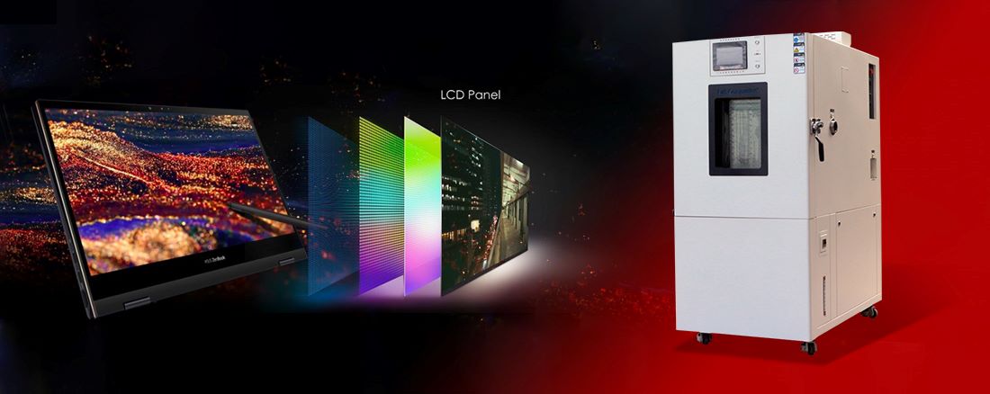
Rechargeable battery, which can be re-active by charging after be used. They are widely used in the fields of environmentally friendly vehicles, power storage, and Dynamic field.
Environmental testing of rechargeable battery is an important means of evaluating their performance under different environmental conditions.
Ⅰ. Testing Purpose
The environmental testing of rechargeable battery aims to simulate various conditions that may be encountered in actual usage environments to evaluate the reliability and performance of the battery. Through testing, it is possible to understand the conditions of working battery under different temperature, humidity, vibration, impact and other conditions, providing scientific basis for the research and development, production and use of battery.
Ⅱ. Testing content
A. Temperature testing
a. High temperature test: Rich a high temperature environment to observe its temperature stability and the risk of thermal runaway.
b. Low temperature testing: Testing the discharge performance, capacity degradation, and low-temperature starting ability of the battery under low temperature conditions.
c. Temperature cycling test: Simulate the temperature changes that the battery may experience in actual use, evaluate its thermal durability and cycle life.
B. Humidity test: Evaluate the battery’s performance, sealing, and corrosion resistance in a humid environments.
C. Vibration testing: Through simulate the battery in the vibration environment that may encounter during transportation, installation, and use, evaluate its structural integrity, electrical connection reliability, and performance stability.
D. Impact testing: Through simulating the battery in unexpected situations such as drops and collisions, and evaluate their impact resistance.
E. External short circuit test: Test the performance of the battery under external short circuit conditions, including risks of thermal runaway and explosion and so on.
Ⅲ. Test standards and specifications
The environmental testing of rechargeable battery should follow relevant testing standards and specifications to ensure the accuracy and comparability of test results. Common testing standards include:
IEC 62133/ IEC 61960、UN 38.3、UL 1642/UL 2580、GB/T 31467、JIS C 8714
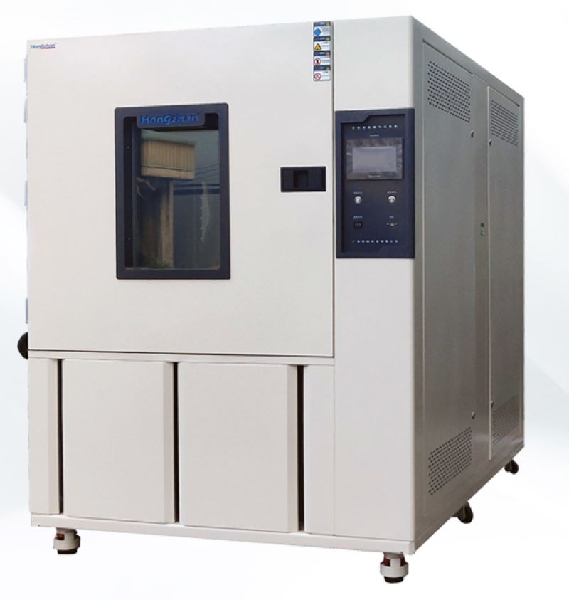
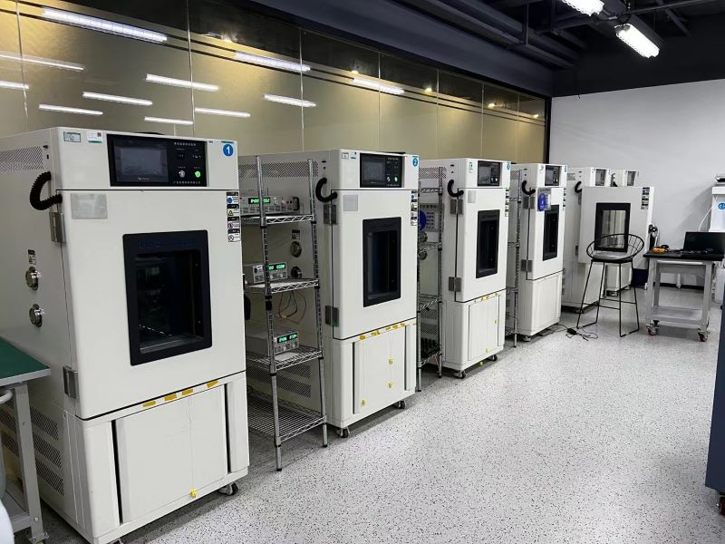
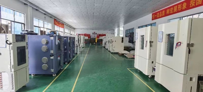
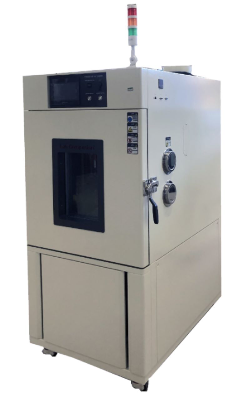
Ⅳ. Test equipment
Environmental testing on rechargeable battery requires the professional testing equipment and methods. Common testing equipment includes:
High and low temperature test chamber: Used to simulate different temperature environments.
Humidity test chamber: used to evaluate the performance of battery in humid environments.
Vibration test bench: Simulate vibration environment to evaluate the structural integrity and performance stability of battery.
Impact testing machine: used to simulate impacts in unexpected situations such as drops and collisions.
Ⅴ. Test results and evaluation
After completing the test, it is necessary to analyze and evaluate the test results. Based on test data and standard requirements, determine whether the performance of the battery meets the requirements under different environmental conditions. For undesirable battery, further analysis and corresponding improvement measures should be taken.
In summary, environmental testing of rechargeable battery is an important means to ensure their stable and reliable performance in practical use. Professional testing instruments can provide more professional, safe, scientific and effective experimental results for rechargeable battery testing, greatly reducing the cost of testing and bringing convenience to companies.
Click to check related products.
https://www.lab-companion.com/thermal-shock-test-chamber
https://www.lab-companion.com/temperature-and-humidity-chamber
https://www.lab-companion.com/rapid-temperature-cycling-test-chamber
Solution to Thermal Shock Test chamber Refrigeration System Blocking
Thermal shock test chamber is generally composed of compressor, air conditioning evaporator, cooler and pipe system software. Refrigeration system blockage generally has two kinds of dirty blockage and ice blockage, and oil blockage is relatively rare.
1. Dirty and blocked
When the compressor of thermal shock test chamber is damaged, and there is waste in the refrigeration system, this waste is very easy to block in the capillary or filter device, which is called dirty plugging. Dirty blockage is because there is residue in the refrigeration system (oxygenated skin, copper chips, welding through), when it is circulated with the refrigerant system, it causes blockage at the capillary or filter device.
Dirty blockage removal method: remove the capillary tube, filter device, cooler, air conditioning evaporator with gas cutting, disassemble the carbon molecular sieve in the capillary tube and filter device, clean the cooler and air conditioning evaporator, carry out dry, vacuum packaging, welding, and fill with refrigerant.
2. Ice jam
Ice blockage is caused by water entering the refrigeration system of thermal shock test chamber. Due to its own with a certain amount of moisture, coupled with the maintenance or refrigerant in the whole process of taking time processing regulations are not tight, so that water and gas into the system software. Under the ultra-high pressure effect of the compressor, the refrigerant is changed from a liquid to a vapor state, so that the water is passed into the narrow and long capillary tubes with the refrigerant circulation system. When the moisture content of each kilogram of refrigerant exceeds 20mg, the filter device is saturated with water, and the water can not be filtered out. When the temperature of the capillary inlet and outlet is 0 ° C, the water is converted from the refrigerant and becomes ice, resulting in ice blocking.
Dirty blocking and ice blocking are divided into full and half blocked, the common fault condition is that the air conditioning evaporator is not frosting or frosting is not full, the temperature behind the cooler is high, and the hand drying filter or capillary entrance feels that the temperature is basically the same as the indoor temperature, sometimes less than the indoor temperature, and a lot of steam is sprayed out of the cutting process pipe. After the ice jam occurs, the friction resistance of the compressor exhaust pipe increases, resulting in the compressor overtemperature, the overload protector is working, and the compressor stops running. After about 25 minutes, a part of the ice jam melts, the compressor temperature decreases, the contact point of the temperature controller and the overload protector is closed, and the compressor starts the refrigerator. Therefore, the ice blockage has regularity, and the air conditioning evaporator can see regular frosting and defrosting conditions.
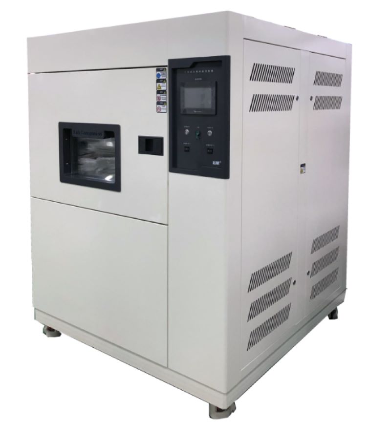
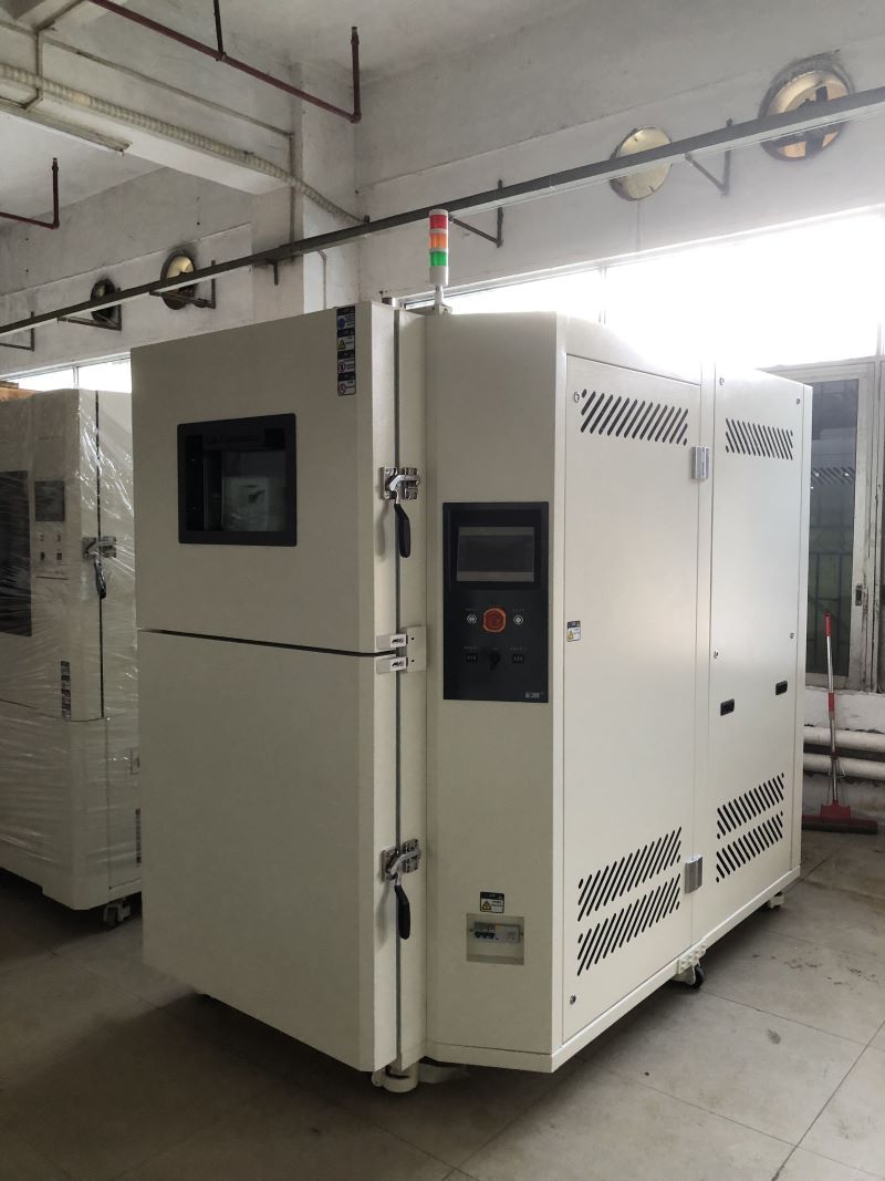
Construction and System Software of Two-zone Thermal Shock Test Chamber
Construction of Two-zone Thermal Shock Test Chamber:
1, Construction mode of environmental test chamber:
Environmental test chamber is composed of a high temperature test chamber located at the upper end, a low temperature test chamber located below, a freezer cabinet located at the back and a home appliance control chamber (system software) located on the right. In this way, the shell occupies a small area, compact structure, beautiful appearance design, the freezer unit is placed in a separate generator chamber body, in order to reduce the vibration and noise of the freezer unit operation on the environmental test chamber harm, in addition to the installation and maintenance of the generator set, the household appliance operation panel is placed on the right panel of the environmental test chamber to facilitate the operation of the actual operation;
2, Shell surface raw materials: cold-rolled plate, surface electrostatic powder spraying solution;
3, The shell cavity raw materials: imported stainless steel plate (SUS304);
4, Thermal insulation material: heat resistant hard plastic polyamine ester foam + foam glass plate;
5, The door: single door, equipped with double silicone rubber sealing and sealing rubber strip heating equipment, under the self-limiting temperature heating zone, to avoid the experiment essence and frost;
6, Test rack: move up and down left and right sliding type stainless steel plate test rack. The pneumatic double-effect cylinder shows a stable and symmetrical driving force. The positioning device of the test rack uses an electromagnetic field triggered limit switch;
7, Cable wire installation hole: the upper end of the test rack and the top of the high temperature test chamber is provided with a telescopic cable threading tube.
Air conditioning system software of two-zone thermal shock test chamber:
1, Gas control method: forced circulation system natural ventilation, balanced temperature control method (BTC). The method refers to the refrigeration unit in the continuous operation of the condition, the automatic control system according to the temperature point set according to the PID automatic and operational output results to manipulate the electric heater's heart output, the ultimate UI will exceed this stable balance.
2, Gas circulation system equipment: embedded central air conditioning room, air supply mode channel and stainless steel plate short-axis exhaust fan, the application of refrigeration unit and kinetic energy adjustment system software, according to the exhaust fan to carry out a reasonable heat exchanger, more than the purpose of maintaining temperature change. According to the improved air flow of the gas, the total gas flow and the working capacity of the heat exchanger with the electric heater and the surface cooler are improved.
3, Evaporative cooling method: fin type air heat exchanger.
4. Gas heating method: select nickel-chromium wire electric heater.
Environmental Test Chambers-Reliability Tests
Environmental resistance test:
Temperature cycle test, temperature and humidity resistance test, impact test
Durability test:
High and low temperature preservation test, continuous switch operation test, continuous action test
Temperature cycle:
a. No boot test: 60℃/6 hours ← Rising and cooling for 30 minutes →-10℃/6 hours, 2cycle
b. Boot test: 60℃/4 hours ← Rising and cooling 30 minutes →0℃/6 hours, 2cycle, power supply without packaging and load
Temperature and humidity test:
No power test: 60℃/95%R.H./48 hours
Boot test: 60℃/95%R.H./24 hours/no packaging power supply load
Impact test: impact distance 3m, slope 15 degrees, six sides
Humidity test: 40℃/90%R.H./8 hours ←→25℃/65%R.H./16 hours, 10cycle)
High and low temperature preservation test: 60℃/95%R.H./72 hours →10℃/72 hours
Continuous switch action test:Complete the switch within one second, shut down for at least three seconds, 2000 times, 45℃/80%R.H.
Continuous action test: 40℃/85%R.H./72 hours/power on
What are the Reliability Tests for Light Emitting Diodes for Communication?
Failure determination of light emitting two tubes for communication:
Provide a fixed current to compare the optical output power, if the error is greater than 10%, the failure is determined.
Mechanical stability test:
Shock test: 5tims/axis, 1500G, 0.5ms Vibration test: 20G, 20 ~ 2000Hz, 4min/cycle, 4cycle/axis Liquid thermal shock test: 100℃(15sec)←→0℃(5sec)/5cycle
Durability test:
Accelerated aging test: 85℃/ power (maximum rated power)/5000 hours, 10000 hours
High temperature storage test: maximum rated storage temperature /2000 hours
Low temperature storage test: maximum rated storage temperature /2000 hours
Temperature cycle test: -40℃(30min)←85℃(30min), RAMP: 10/min, 500cycle
Moisture resistance test: 40℃/95%/56 days, 85℃/85%/2000 hours, sealing time
Communication diode element screening test:
Temperature screening test: 85℃/ power (maximum rated power)/96 hours screening failure determination: Compare the optical output power with the fixed current, and determine failure if the error is larger than 10%
Communication diode module screening test:
Step 1: Temperature cycle screening: -40℃(30min)←→85℃(30min), RAMP: 10/min, 20cycle, no power supply
Second: Temperature screening test: 85℃/ power (maximum rated power)/96 hours
Industrial Computer Reliability Test Solutions
Industrial computers can be divided into three categories according to their application attributes:
(1) Board class: includes Single Board Computer (SBC), Embedded board (Embedded Board), Black Plane, PC/104 module.
(2) Subsystem class: includes single-board computers, boards, chassis, power supplies and other peripherals combined into operational subsystems, such as industrial servers and workstations.
(3) System integration solutions: refers to a set of systems developed for a professional field, including the required software and hardware and surrounding, such as automatic teller machines (ATMs). The application of industrial computers widely covers ATM, POS, medical electronic equipment, game machines, gambling equipment, etc. The multi-field industry makes industrial computers must be able to withstand the use of sunlight, high and low temperature, wet and other environments, so the relevant reliability test is the focus of various manufacturers in the research and development test.
Common reliability tests for industrial computers:
Wide temperature test
Wide temperature range: according to the actual application environment can be divided into four categories:
1, Outdoor: especially for the extreme low temperature or high temperature areas, such as northern Europe and desert countries, the temperature range can be from -50 to 70°C.
2, Confined Spaces: for example, where a heat source is generated, such as near a boiler, the high temperature range is about 70°C3. Mobile equipment: such as vehicle equipment, the high temperature can be 90°C4 depending on the car area. Special harsh environment: such as aerospace equipment, oil drilling equipment.
Aging stress test
Aging stress test: The temperature range is from -40°C to 85°C, and the temperature variation rate is 10 °C per minute for cyclic testing
Constant temperature and humidity machine - standard type
The purpose of the machine is to simulate the product under the combined conditions of temperature and humidity in the climate environment (high and low temperature operation & storage, temperature cycle, high temperature and high humidity, low temperature and low humidity, dew test... Etc.), to detect whether the adaptability and characteristics of the product itself have changed. ※ Must meet the requirements of international standards (IEC, JIS, GB, MIL...) To achieve international consistency of measurement procedures (including test procedures, conditions, methods)
Test item: Wide temperature test
Thermal shock machine - stress screening testing machine
Temperature cycling stress screening is the product in the design strength limit, the use of temperature acceleration technology (in the upper and lower extremal temperature of the cycle, the product produces alternating expansion and contraction) to change the external environmental stress, so that the product produces thermal stress and strain, By accelerating the stress to make the potential defects in the product emerge [potential parts material defects, process defects, process defects], in order to avoid the product in the use process, the test of environmental stress sometimes lead to failure, causing unnecessary losses, for improving the product delivery yield and reducing the number of repair has a significant effect, in addition, the stress screen itself is a process stage process. Rather than a reliability test, stress screening is a 100% procedure performed on the product.
Test item: Aging stress test
Cleaning Method of Condenser in Rapid Temperature Change Test Chamber
Rapid temperature change test chamber is a kind of high-precision and high-stability experimental equipment, which can carry out temperature changes in a short time to test the performance changes of materials and products at different temperatures. It is mainly used to detect the performance of products under rapid temperature changes and limit temperature conditions, and is widely used in semiconductor chips, scientific research institutions, quality inspection, new energy, optoelectronic communications, aerospace military industry, automotive industry, LCD display, medical and other science and technology industries.
After handing over the machine to the customer, in addition to instructing the precautions of equipment operation, it will also emphasize the daily maintenance of the equipment. After a long period of operation, Rapid temperature change test chamber should pay special attention to the maintenance of the refrigeration system, because the refrigeration system is not only a complex manufacturing process but also the core of the equipment refrigeration, and the next will focus on understanding the cleaning method of the condenser in the refrigeration unit.
1, Chemical pickling and scaling
For vertical and horizontal shell and tube condensers, the chemical pickling method can be used, and the weakly acidic detergent can be prepared in the pickling tank. After the pickling pump is turned on and run for 24 hours, the pickling pump is turned off, and the circular steel brush is used to brush the tube wall of the condenser back and forth, and the water is washed until all the dirt or rust stains and the scaling solution remain in the tube are clean.
2, Mechanical scaling
First, the refrigerant in the vertical shell and tube condenser is extracted, and all the valves connected to the condenser are closed, and then cooling water is normally supplied to the condenser. Use the bevel gear connected with the flexible shaft pipe washer (the diameter of the hob should be selected to be smaller than the inner diameter of the cooling pipe to scratch the inner wall) in the condenser from the top down rotary rolling mode to remove scale, because the circulating cooling water and the friction of the pipe wall generate heat, can help dirt and rust and other dirt directly washed out of the pool. After the end of descaling, drain the water in the condensate pool, clean up the dirt, and refill the water.
3, Electronic magnetic water scaling
At normal temperature, the electron magnetic water can dissolve calcium, magnesium and other salts in the cooling water of the condenser as positive and negative ions in the water. Electron magnetic water can change its crystallization conditions, can loosen the structure, reduce the tensile and compressive capacity, so that it can not form a hard scale with strong bonding force, and is converted into loose mud with the flow of cooling water and discharged.
The above is the scientific method of cleaning the condenser dirt of rapid temperature change test chamber.
Heat Dissipation Method of Thermal Shock Test Chamber Refrigeration Unit
Generally speaking, thermal shock test chamber is divided into two refrigeration methods: air-cooled and water-cooled. The accuracy of the test results not only depends on the excellent process quality of the equipment itself, but also is closely related to the cooling efficiency of the refrigeration unit. So what factors affect the heat dissipation efficiency?
In short, the air-cooled type has the greatest impact on its heat dissipation efficiency or environmental factors. For water-cooled refrigeration units, the key factor is the water tower configured as a fixed equipment, the following is the method of improving the heat dissipation efficiency of different cooling methods.
Firstly, air-cooled thermal shock test chamber:
Reason: Because the heat dissipation of the air-cooled refrigeration unit mainly relies on the electronic fan to dissipate a large amount of heat through the fin. If the environment is very dusty, the equipment is affected by the wind, a lot of dust will adhere to the fan and fins. Although less dust does not have any effect on the air-cooled refrigeration unit, when the dust on the fins continues to increase, it will directly affect the heat dissipation effect of the air-cooled refrigeration unit, resulting in poor heat dissipation effect and the corresponding cooling capacity.
1, The user should provide a relatively clean use environment for the air-cooled refrigeration unit (smooth ventilation is the best), and try to stay away from the harm of all kinds of dust. This will extend the frequency of inefficient operation of air-cooled refrigeration units because there is more dust in the environment, and give the unit equipment a safe and stable operation environment.
2, Keep the equipment clean and tidy, and clean the fins regularly. Can be washed with wind and tap water, if the environment is harsh, the dust impurities on the fins are more oil, then rinse with tap water first, and then spray on cleaning dust, after 10 minutes or so, and then repeatedly rinse with tap water. After using the air-cooled refrigeration unit for a period of time, it is necessary to carry out a comprehensive cleaning for the environment and the machinery and equipment.
Secondly, water-cooled thermal shock test chamber:
Reason: Since most of the water tower is installed outside, it needs to withstand strong light radiation, higher temperature, and fast water evaporation, which is easy to cause insufficient water flow in the cooling water circulation, and finally cause poor cooling effect and even high pressure alarm.
1, Timely water supply.
2, Check whether the water supply valve is abnormal.
3, Check the running status of the water tower, if abnormal, it needs to be adjusted to normal state in time.
4, Clean the pipeline filter.
5, Keep the water source clean.
The main policy to improve the heat dissipation efficiency of the air-cooled thermal shock test chamber is to place the chiller outdoors, avoid direct sunlight as far as possible, and make a protective shed for the equipment if conditions exist. If it must be placed indoors, it is better to put it next to the window to maintain good ventilation, or install an air pipe to draw hot air to the outside.
The Role of High and Low Temperature Test Chamber for Electronic Component Testing
High and low temperature test chamber is used for electronic and electrical components, automation parts, communication components, automotive parts, metal, chemical materials, plastics and other industries, national defense industry, aerospace, military, BGA, PCB substrate wrench, electronic chip IC, semiconductor ceramic magnetic and polymer material physical changes. Testing the performance of its material to withstand high and low temperatures and the chemical changes or physical damage of the product in thermal expansion and contraction can confirm the quality of the product, from precision ics to heavy machinery components, will be an essential test chamber for product testing in various fields.
What can the high and low temperature test chamber do for electronic components? Electronic components are the foundation of the whole machine and may cause time - or stress-related failures during use due to their inherent defects or improper control of the manufacturing process. To ensure the reliability of the entire batch of components and meet the requirements of the entire system, you need to exclude the components that may have initial faults under operating conditions.
1. High temperature storage
The failure of electronic components is mostly caused by various physical and chemical changes in the body and surface, which are closely related to temperature. After the temperature rises, the chemical reaction speed is greatly accelerated, accelerating the failure process. The defective components can be exposed in time and eliminated.
High temperature screening is widely used in semiconductor devices, which can effectively eliminate failure mechanisms such as surface contamination, poor bonding and oxide layer defects. Generally stored at the highest junction temperature for 24 to 168 hours. High temperature screening is simple, inexpensive and can be carried out on many parts. After high temperature storage, the parameter performance of components can be stabilized and the parameter drift in use can be reduced.
2. Power test
In the screening, under the combined action of thermoelectric stress, many potential defects of the body and surface of the component can be well exposed, which is an important project of reliability screening. Various electronic components are usually refined for a few hours to 168 hours under rated power conditions. Some products, such as integrated circuits, can not arbitrarily change the conditions, but can use high temperature working mode to increase the working junction temperature to achieve a high stress state. Power refining requires special test equipment, high and low temperature test chamber, high cost, screening time should not be too long. Civilian products are usually a few hours, military high-reliability products can choose 100,168 hours, and aviation-grade components can choose 240 hours or longer.
3. Temperature cycle
Electronic products will encounter different ambient temperature conditions during use. Under the stress of thermal expansion and contraction, components with poor thermal matching performance are easy to fail. Temperature cycle screening utilizes the thermal expansion and contraction stress between extreme high temperature and extreme low temperature to effectively eliminate products with thermal performance defects. The commonly used component screening conditions are -55~125℃, 5~10 cycles.
Power refining requires special test equipment, high cost, screening time should not be too long. Civilian products are usually a few hours, military high-reliability products can choose 100,168 hours, and aviation-grade components can choose 240 hours or longer.
4. The necessity of screening components
The inherent reliability of electronic components depends on the reliability design of the product. In the manufacturing process of the product, due to human factors or fluctuations in raw materials, process conditions, and equipment conditions, the final product can not all achieve the expected inherent reliability. In every batch of finished products, there are always some products with some potential defects and weaknesses, which are characterized by early failure under certain stress conditions. The average life of early failed parts is much shorter than normal products.
Whether electronic equipment can work reliably depends on whether electronic components can work reliably. If the early failure parts are installed together with the whole machine equipment, the failure rate of the early failure of the whole machine equipment will be greatly increased, and its reliability will not meet the requirements, and it will also pay a huge price to repair.
Therefore, whether it is a military product or a civilian product, screening is an important means to ensure reliability. High and low temperature test chamber is the best choice for the environmental reliability test of electronic components.
Setting and Maintenance of Constant Temperature and Humidity Test Chamber
Constant temperature and humidity test chamber is a relatively precise test equipment. In order to ensure the smooth completion of each test process, the power supply of the connected equipment must be stable at around 380V to ensure that the compressor will not be damaged. In addition, you must ensure the personal safety of the personnel who receive the power, so please understand the specific operation methods before wiring.
Constant temperature and humidity test chamber adjust or replace the connected power supply. After checking that the voltage of the power supply to be connected is correct, connect the neutral terminal to the neutral terminal in the distribution chamber. Ensure that the neutral line is connected, otherwise it may cause the equipment of the constant temperature and humidity test chamber to fail to work normally or burn electrical components.
After confirming that the neutral wire is connected, connect the 3 ∮ wire to the three terminals under the main switch of the distribution chamber in the constant temperature and humidity test chamber, and tighten the screws. We need to connect the ground wire, which is connected in the same way as other power cables, and directly to the ground terminal of the distribution chamber. In the process of connecting each power cord, everyone must ensure that the different colors of the power cord can be correctly identified to avoid connection errors and normal testing.
Maintenance of constant temperature and humidity test chamber:
1, Clean the water circulation system: clean the water filter, replace the filter, check the operation of the pump, including the operation of the water flow switch, adjust the water circulation flow and test operation.
2, Check all electrical wiring and electrical components to ensure reliable operation and good contact.
3, Replace the fresh air filter.
4, Refrigeration system cleaning: replace the refrigeration oil, clean the oil filter.
5, Check the vulnerable parts of the refrigeration system: check the sealing condition of the compressor and connecting parts, and replace all filters.
6, Refrigeration system leakage inspection: check all the connecting parts of the refrigeration system and the connecting parts of the valve plate are leaked and tightened.
7, According to the working conditions to supplement refrigerant: check whether the need to supplement the system refrigerant to ensure effective cooling capacity.
8, Comprehensive system operation: check whether the operating components are in good condition.
Influence of Capillary Length of High and Low Temperature Test Chamber on Parameters of Refrigeration System
1. Influence on suction and exhaust temperature and pressure
With the same charge amount, the shorter the capillary, the larger the refrigerant flow rate, so the suction temperature and exhaust temperature will decrease; Similarly, when the capillary is constant, the larger the charge amount is, the larger the refrigerant flow rate is, and the suction temperature and exhaust temperature also decrease.
However, with the increase of flow, the inspiratory pressure also rises. For the exhaust pressure, the shorter the capillary is, the smaller the filling amount is. When the capillary length is constant, the higher the charge amount is, the higher it is.
2. Influence on condensing temperature and pressure
When the refrigerant charge is constant, the shorter the capillary tube is, the condensation temperature and pressure decrease.
When the capillary length is constant, the higher the charge amount, the higher the condensing temperature and pressure.
3. Influence on evaporation temperature and pressure
The shorter the capillary, the greater the evaporation temperature and pressure.
When the capillary length is constant, the higher the charge amount, the higher the evaporation temperature and pressure.
4. the influence of supercooling and superheat
When the refrigerant charge is constant, the longer the capillary is, the higher the supercooling degree and the superheat degree are.
When the capillary length is constant, the higher the charge amount, the greater the supercooling degree and the smaller the superheat degree.
5. Influence on cooling capacity, power consumption and performance coefficient EER
When the refrigerant charge is constant, the longer the capillary length, the smaller the power consumption, but the cooling capacity is also smaller, the EER is smaller.
When the charge amount increases to a certain extent, because of the influence of heat exchange temperature difference, the cooling capacity increases, and the EER also increases.
6. Design points of capillary system
(1) On the high pressure side, the reservoir is generally not used, in fact, whether the reservoir is used does not depend on what kind of throttling device, but depends on whether the operation of the entire system is needed, such as heat pump system, shutdown pump system.
(2) In the suction tube, it is best to use a gas-liquid separator.
Because when the capillary system is shut down, the high and low pressure side will balance and the evaporator will accumulate refrigerant liquid, the gas-liquid separator can prevent liquid shock and refrigerant migration.
(3) The high pressure side can accommodate all the refrigerant charged, which is to prevent the capillary blockage when the damage to the high pressure piping system and compressor.
(4) In the high load condition of the evaporator, because the capillary system can be fed back to the condenser side, the condenser should take into account whether the condensing pressure will be too high under this condition, so it is necessary to increase the condensing heat transfer area.
(5) The pipe between the condenser outlet and the capillary inlet should not accumulate refrigerant liquid.
One is that when the compressor is shut down, this part of the refrigerant liquid will evaporate because of the pressure drop, flow into the evaporator and condense, thus bringing some heat to the refrigeration space, which may have an impact on the closed space of the refrigerator, for the air conditioning, this part of the heat can be ignored;
Another is that this will delay the time of the balance of the high and low voltage side, which may cause problems when the low torque compressor starts again, which can generally be solved by increasing the delay in the control (in fact, this is also good for reducing the impact of the starting current on other electrical appliances or the grid).
(6) The capillary inlet must be filtered to prevent clogging, especially the HFC refrigerant used now, which is required to add a dryer in design.
(7) Before the refrigerant enters the capillary, it is best to have a certain degree of undercooling, which can be added to the evaporator by adding a section of undercooling tube, or generating heat exchange with the suction tube, so that the gas flash in the capillary is minimal, thereby increasing the cooling capacity and ensuring the refrigerant flow.
However, it should be noted that at low temperature conditions, the undercooling may be too large because there is a little return liquid in the suction tube, which increases the capillary flow rate, and in turn increases the undercooling degree, which may eventually cause the return liquid.
Maintenance Method of High and Low Temperature Test Chamber
There are three common types of high and low temperature test chamber controllers: software failure, system failure and hardware failure.
1, Software failure:
Software failure mainly refers to the controller failure of the high and low temperature test chamber, including the internal parameters, the control point IS control and output signal of the solenoid valve on and off.
2, System failure:
System failure refers to the initial design problems of the refrigeration system, including the leakage of refrigerant caused by high and low temperature test chamber does not cool down, and refrigerant leakage is often due to transport and high and low temperature test chamber operation jitter or refrigeration copper pipe welding process is not fine and other reasons caused.
3, Hardware failure:
Hardware failure may lead to non-cooling hardware compressor, solenoid valve and other refrigeration components.
Then the user can listen and touch to roughly understand what is the hardware high and low temperature test chamber damage, if it is a compressor failure, the compressor sound will be abnormal or do not work does not start or the compressor itself temperature is much higher than usual temperature, and the solenoid valve failure and other refrigeration components failure users are not too good to master.
In addition, the damage of the controller and the damage of the electronic parts of the control refrigeration system may also cause the phenomenon of non-cooling and non-cooling of the high and low temperature test chamber.
Scientific principle of heating and cooling of high and low temperature test chamber:
The high and low temperature test chamber has the functions of heating, cooling, humidification and dehumidification, and can detect the product's high temperature resistance, low temperature resistance and humidity resistance. How is the temperature in the high and low temperature test chamber controlled?
The heating device is the key link to control whether the high and low temperature test chamber is heated up. The controller outputs voltage to the relay when it gets the heating instruction. The high and low temperature test chamber is about 3-12 volts of direct current added to the solid state relay. The AC end of the high and low temperature test chamber is equivalent to a wire connection, and the contactor is also drawn at the same time. Heat up the constant temperature and humidity test chamber.
Cooling is an important part of the high and low temperature test chamber, which directly affects the determination of a high and low temperature and performance, including compressor, condenser, throttling device, evaporator four major components, compressor is the heart of the refrigeration system, it inhales low temperature and low pressure gas, into high temperature and high pressure gas, through condensation into a liquid to release heat, through the fan to take away heat, Therefore, the test chamber is the reason of hot air, and then become low pressure liquid through throttling, and then become low temperature and low pressure gas through the evaporator back to the compressor, the refrigerant in the evaporator to absorb the heat of the high and low temperature chamber to complete the gasification process and absorb heat, to achieve the purpose of refrigeration, to complete the high and low temperature test chamber cooling process.
High and low temperature chamber temperature and cooling rate test procedure:
In the adjustable range of the temperature of the test chamber, the lowest nominal temperature was selected as the lowest cooling temperature, and the highest nominal temperature was selected as the highest heating temperature.
Open the cold source, so that the test chamber from room temperature to the lowest cooling temperature, stable for at least 3 hours, rise to the highest heating temperature, stable for at least 3 hours and then to the lowest cooling temperature, during the heating and cooling, record once a minute, until the end of the test process.
The principle of high and low temperature test chamber heating and cooling is so, the realization of its function is completed by the setting of the control system, understanding the principle of heating and cooling, in the use of high and low temperature test chamber must be more handy.


 Get A Quote


 IPv6 network supported