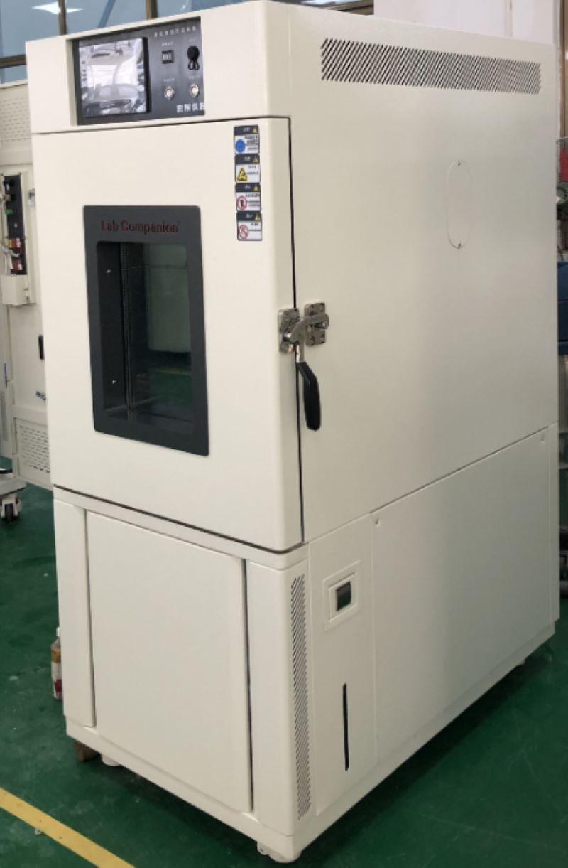
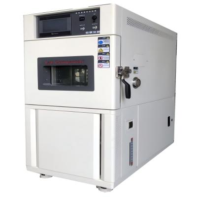
Definition and Use of Temperature Cycling Test Chamber
Temperature cycling test chamber is a kind of laboratory equipment widely used in various industries, its main function is to cycle the product within a certain temperature range to simulate the operation of the product in different temperature environments. The equipment is an important tool to realize product reliability testing, quality control and product performance evaluation.
The temperature cycling test chamber is widely used and can be used for testing in various fields, such as aerospace, automotive, electronics, electric power, medical and other fields. In the aerospace sector, temperature cycle test chambers are used to test the performance of aircraft components at extreme temperatures to ensure their reliability in extreme environments. In the automotive field, the temperature cycle test chamber is used to test the performance of automotive components under different temperature and humidity conditions to ensure that the car can operate normally in a variety of environments. In the field of electronics and power, temperature cycling test chambers are used to test the performance and reliability of electronic equipment under different temperature conditions to ensure that the equipment can operate stably for a long time. In the medical field, temperature cycling test chambers are used to test the performance and reliability of medical equipment under different temperature and humidity conditions to ensure the normal operation of the equipment.
The working principle of the temperature cycling test chamber is to carry out the cycling test by controlling the temperature and humidity in the chamber. The device has a variety of temperature control modes, such as constant temperature control, programmed temperature control, programmed temperature control, etc., which can be selected according to needs. During the test process, the temperature cycling test chamber will place the product in different temperature environments for testing to simulate the use of the product in different environments. After the test is completed, users can improve and upgrade the product according to the test results to improve the reliability and performance of the product.
In short, the temperature cycling test chamber is a laboratory equipment widely used in various industries, and its main function is to cycle the product within a certain temperature range to simulate the operation of the product in different temperature environments. The equipment can be used for testing in various fields, such as aerospace, automotive, electronics, power, medical and other fields, and is an important tool to achieve product reliability testing, quality control and product performance evaluation.
Working Principle and Classification of Vacuum Pump in Vacuum Drying Oven
1, The working pressure of the vacuum pump should meet the limit vacuum and working pressure requirements of the vacuum equipment, and the best value of the vacuum degree of the selected vacuum pump is 133pa=-0.1 mpa. Usually, the vacuum degree of the selected pump is half to an order of magnitude higher than the vacuum degree of the vacuum equipment.
2, Correctly select the working point of the vacuum pump. Each pump has a certain operating pressure range.
3, The vacuum pump under its working pressure, should be able to discharge all the gas generated in the process of vacuum equipment.
4, Correctly combine the vacuum pump. Because the vacuum pump has selective pumping, sometimes a pump can not meet the pumping requirements, and several pumps need to be combined to complement each other to meet the pumping requirements, such as titanium sublimation pump has a high pumping speed for hydrogen, but can not pump helium, and the three-pole sputtering ion pump, (or bipolar asymmetric cathode sputtering ion pump) has a certain pumping speed for argon, the combination of the two, It will make the vacuum device get a better vacuum degree. In addition, some vacuum pumps can not work at atmospheric pressure, need pre-vacuum; Some vacuum pump outlet pressure is lower than atmospheric pressure, the need for the front pump, so it is necessary to combine the pump to use.
5, Vacuum equipment for oil pollution requirements. If the equipment is strictly required to be oil-free, a variety of non-oil pumps should be selected, such as: water ring pumps, molecular sieve adsorption pumps, sputtering ion pumps, cryogenic pumps, etc. If the requirements are not strict, you can choose to have a oil pump, plus some anti-oil pollution measures, such as cooling trap, baffle, oil trap, etc., can also meet the clean vacuum requirements, our company's vacuum drying oven selection is rotary vane oil pump, its main characteristics: large force, fast speed, high efficiency.
6, Understand the composition of the gas being pumped, whether the gas contains condensable steam, whether there is particulate dust, whether there is corrosion, etc. When selecting a vacuum pump, you need to know the gas composition, select the appropriate pump for the gas being pumped. If the gas contains steam, particles, and corrosive gases, it should be considered to install auxiliary equipment on the pump inlet line, such as condenser, dust collector, or liquid water filter.
7, What is the impact of the oil steam discharged from the vacuum pump on the environment? If the environment is not allowed to have pollution, you can choose an oil-free vacuum pump, or exhaust the oil steam to the outside.
8, Whether the vibration generated by the vacuum pump during operation has an impact on the process and the environment. If the process does not allow, should choose non-vibration pump or take anti-vibration measures.
9, The price of vacuum pump, operation and maintenance costs.
The Measuring Principle of Hygrometer in High and Low Temperature Test Chamber
Temperature and humidity is the percentage of the amount of water vapor (vapor pressure) contained in a gas (usually air) and the amount of saturated water vapor (saturated vapor pressure) in the same case as the air, expressed in RH%. Humidity long ago had a close relationship with life, but it was difficult to quantify it. The expression of humidity is humidity, relative humidity, dew point, ratio of moisture to dry gas (weight or volume), and so on.
Humidity measurement method hygrograph humidity measurement from the principle of the division of twenty or thirty. But humidity measurement is always one of the difficult problems in the world measurement field. A seemingly simple quantity value, in depth, involves quite complex physico-chemical theoretical analysis and calculation, beginners may ignore many factors that must be paid attention to in humidity measurement, thus affecting the reasonable use of sensors.
Common humidity measurement methods are: dew point method, wet and dry bulb method and electronic sensor method, dynamic method (double pressure method, double temperature method, shunt method), static method (saturated salt method, sulfuric acid method)
1, Dew point method hygrograph: is to measure the temperature when the wet air reaches saturation, is a direct result of thermodynamics, high accuracy, wide measurement range. Precision dew point instrument for measurement can reach ±0.2°C or even higher accuracy. However, the cold mirror dew-point meter with modern optoelectric principle is expensive and often used with standard humidity generators.
2, Wet and dry bulb hygrometer: this is a wet measurement method invented in the 18th century. It has a long history and is widely used. Wet and dry bulb method is an indirect method, which converts the humidity value from the wet and dry bulb equation, and this equation is conditional: that is, the wind speed near the wet bulb must reach more than 2.5m/s. The common wet and dry bulb thermometer simplifies this condition, so its accuracy is only 5~7%RH, and the wet and dry bulb does not belong to the static method, do not simply think that improving the measurement accuracy of the two thermometers is equal to improving the measurement accuracy of the hygrometer.
3, Electronic humidity sensor method hygrometer: electronic humidity sensor products and humidity measurement belong to the industry that rose in the 1990s in recent years, at home and abroad in the field of humidity sensor research and development has made great progress. Humidity sensors are developing rapidly from simple humidity sensors to integrated, intelligent, multi-parameter detection, creating favorable conditions for the development of a new generation of humidity measurement and control systems, and also raising humidity measurement technology to a new level.
4, Double pressure method, double temperature hygrometer: is based on the thermodynamic P, V, T balance principle, the balance time is longer, shunt method is based on the precise mixing of moisture and dry air. Due to the use of modern measurement and control means, these devices can be quite precise, but because of the complex equipment, expensive, time-consuming operation, mainly used as standard measurement, its measurement accuracy can reach ±2%RH or more.
5, Static method of saturated salt hygrometer: is a common method in humidity measurement, simple and easy. However, the saturated salt method has strict requirements for the balance of liquid and gas two phases, and high requirements for the stability of ambient temperature. It requires a long time to balance, and low humidity points require even longer. Especially when the humidity difference between the indoor and the bottle is large, it needs to be balanced for 6 to 8 hours each time it is opened.
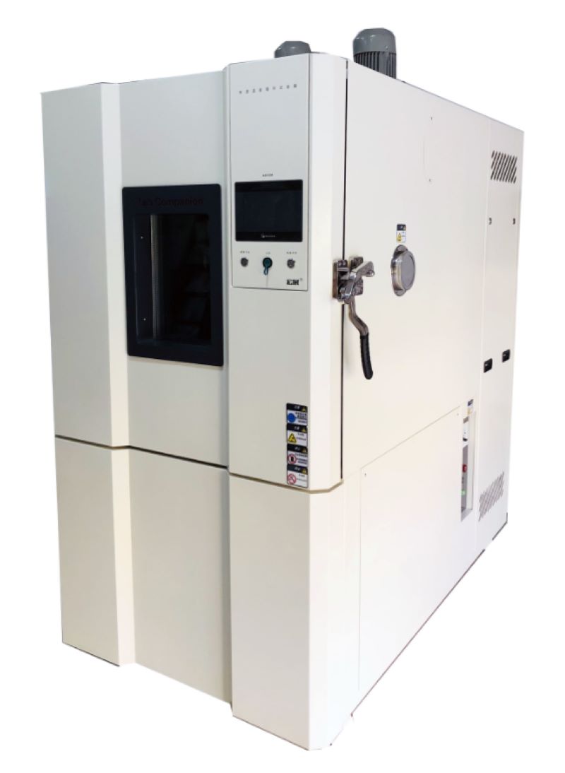
Display and Heating System of Temperature and Humidity Test Chamber
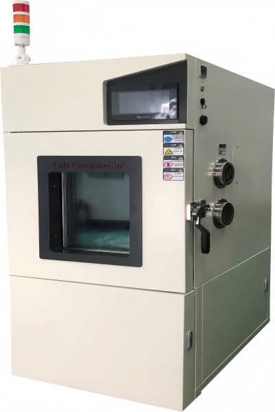
The display and control interface of temperature and humidity test chamber is intuitive and clear, and the light touch selection menu is simple and easy to use, and the performance is stable and reliable. Flexible program control, to bring users stable performance, flexible control, cost-effective products. The input channel and output channel can be expanded arbitrarily. It is a test equipment for aviation, automotive, home appliances, scientific research and other fields, used to test and determine the parameters and performance of electrical, electronic and other products and materials after temperature environment changes in high temperature, low temperature, alternating temperature and humidity degree or constant test.
Product features:
1, Use CNC cutting, laser opening, mass production test chamber.
2, Spray strictly use outdoor powder, powder is not recycled once use, strong adhesion without variegation.
3, The visual window frame is made of one-time opening mold, which has a strong industrial sense.
4, The instrument panel made of one-time mold is beautiful and generous. The label on the instrument panel uses PVC stickers and the back glue uses 3M glue.
5, The caster adopts the free adjustment height caster made by Qidong Baiyun Electronics original factory, non-market counterfeit products, high quality, beautiful and generous.
6, All the standard drawings of the refrigeration system are welded to ensure that the piping of each equipment is consistent, and the refrigeration performance has reached the appropriate state.
7, Wiring of all the standard drawings of the electrical system, thirteen inspection processes after the completion of wiring to ensure accurate wiring and no trouble.
8, The water system uses three cups to control the water level to ensure that the humidifier water supply is separated from the wet bulb water level. The temperature fluctuation caused by humidifier water is avoided.
Display:
1, The original brand temperature and humidity meter, 5.7-inch high-definition true color LCD touch screen.
2, Real-time monitoring (monitoring controller real-time data, signal point status, actual output status).
3, The controller can store the historical data within 600 days (when the temperature and humidity data are recorded at the same time at a recording interval of more than 1 minute in 24-hour operation), and can play back the uploaded historical data curve.
4, The exported files can be viewed on the computer or converted into EXCEL format by random gift software.
5, Instrument equipped with RS232/485 port.
6, With automatic calculation function, the temperature and humidity change conditions can be corrected immediately, so that the temperature and humidity control is more safe and stable.
Heating system:
1, The use of far infrared nickel alloy high-speed heating (2KW×2) electric heater;
2, High temperature independent system, does not affect low temperature test, high temperature test and alternating temperature and humidity;
3, Temperature and humidity control output power is calculated by microcomputer to achieve high precision and high efficiency.
High Pressure Failure Caused by Water Cooling Unit of High and Low Temperature Test Chamber
1, High and low temperature test chamber refrigerant charging too much. Such a thing is usually produced after the overhaul, mainly manifested as the suction and exhaust pipe working pressure, balanced working pressure are high, refrigeration compressor operation current is also high.
Solution: Air should be released under the rated load according to the working pressure and balanced working pressure of the suction and exhaust pipe and its operating current until normal.
2, The water cooling temperature of the high and low temperature test chamber is too high, and the actual condensation effect is poor. The cooling water rated load of the refrigeration unit is 40~45'C, the temperature is high, and the heat pipe is not good at heat dissipation, which must cause high condensing pressure, and this phenomenon is therefore generated in the high temperature season.
Solution: The reason for the high temperature will be: the common faults of the closed cooling tower, such as the centrifugal fan is not turned on so that the water distributor does not turn, mainly manifested in the high temperature of the cooling circulating water and the rapid rise; The average external temperature is high, the waterway is short, and the water flow of the circulating system is small, so the cooling circulating water temperature is usually maintained at a high level, and the method of upgrading the storage pool can be treated.
3, The water cooling of the high and low temperature test chamber is not enough, and the water yield cannot reach the rated value. The specific performance is that the difference of water pressure in and out of the generator set is reduced (compared with the pressure difference at the beginning of the operation of the system software fund), and the temperature difference is increased.
Solution: The reason for the insufficient water output is that the system software has less water or gas. The solution is to install an automatic exhaust valve in the upper air of the pipeline to develop the exhaust pipe; The pipeline filter is blocked or used too thin, the water permeability working capacity is limited, should use a suitable filter device and clear the q filter screen every quarter; The centrifugal pump is small and does not match the system software.
4, High and low temperature test chamber cooler fouling or blocking. Condensate water is usually used in drinking water, at about 40°C is very easy to accumulate scale, and because the closed cooling tower is vertical, it is immediately exposed to the gas, dirt and dirty things are very easy to enter the cooling system, resulting in the cooler dirty blocked, the total heat transfer area is small, low efficiency, and also harm the water output. Its main performance is that the generator set inlet and outlet water pressure difference, the temperature difference increases, the temperature of the hand cooler is very high, and the copper pipe of the cooler exhaust air conditioning is hot.
Solution: Reverse cleaning of the generator set should be carried out every quarter, and chemical cleaning scale cleaning should be carried out if necessary.
How to Control the Uniformity of Temperature and Humidity When the High and Low Temperature Test Chamber is Loaded?
High and low temperature test chamber "load" refers to the weight of our test product, or the product needs to be energized to test its heat is referred to the load. The "load" in the high and low temperature chamber is divided into non-heating load and heating load, and the test product that is not powered on or powered on is called non-heating load. This load has no effect on the temperature and humidity range of the constant temperature and humidity test chamber as a whole, but only affects the time of rising and cooling or rising and falling humidity. The test product that needs to be powered on and emits heat is a heating load, which has a relatively large impact on temperature and humidity, and the load that different temperature points or humidity points can withstand is not the same.
It is very important to select the appropriate test equipment when the product is undergoing temperature test.
1, The test range must be required to meet the product failure possibility test range, that is, whether it is a high temperature chamber or a low temperature chamber or a temperature and humidity test chamber or a thermal shock test chamber should be able to meet the extreme temperature conditions specified in the test requirements.
2, Ensure the volume of the test sample, it should not be greater than the working volume of the test equipment 1/5 of the principle standard to select the test equipment.
3, In order to ensure the uniformity of temperature in the test area, the convection mode of the test chamber is customized according to the heating power of the sample. The natural convection of hot air is used, which is especially suitable for drying powder, and most of the test equipment adopts the forced circulation of hot air. The difference in the temperature distribution of the equipment has a great impact on the test results. When a large sample is used, or the number of samples tested at the same time is large, the test results will vary greatly with the different locations, so the temperature uniformity of the equipment should be selected as best as possible. The uniformity performance of the high and low temperature alternating and humidity test chamber of the macro exhibition instrument can reach ≤0.5°C.
4, To prevent the sample heat absorption or heat release caused by heat radiation or heat load in the test area, the heating or refrigeration system device of the equipment has no effect on the temperature equalization and cooling rate of the sample during the test.
We can not be empty when using the high and low temperature test chamber, we will more or less place the test sample, and the user - generally after the test sample put into the heat is not too much concept, in order to avoid the temperature can not reach, can not fall down or rise and cool slowly this kind of situation, so we recommend that when purchasing equipment, to its heat requirements, or place the material, weight, size of the sample to tell the manufacturer, which will effectively help the test to make the test effect better.
Composition of Electrical Components of High and Low Temperature Test Chamber
The main parts of high and low temperature test chamber are refrigeration units, condensers, evaporators, and controllers. The main parts play a key role, so everyone pays special attention to its main parts raw materials. However, most of them ignore its auxiliary parts at this time, or feel that the role of auxiliary parts is not worth noting. Few people want to count the specific parts, so it is not clear what specific electronic components are fully used in the constant temperature and humidity test chamber.
1, Refrigeration unit:
Used to control the operation of refrigeration unit, to carry out refrigeration cycle, and there are single-phase and three-phase.
2, Fan motor:
Used to control the fan circulation steam body, heat exchanger heat conduction, and there are indoor and outdoor.
3, Electric heater equipment:
Used for heating indoor air quality quality, tubular, flocculent points.
4, Timer:
Used for automatic control system timing boot.
5, DC contactor:
Used for refrigeration unit motor breaking and connection.
6, Leakage protector power switch:
It can not only connect or disconnect the main circuit like other switches, with the effect of leakage current detection and discrimination, when the main control circuit caused by power outage or cable sheath damage, leakage protection switch power supply main switch can be connected or disconnected switch components according to the identification results. It can be combined with isolation switch and heat relay to form a full-function low-voltage switching electronic device.
7, Overtemperature protection equipment:
Its role can not be ignored, when the controller temperature is not sensitive, the implementation of the E double maintenance of the box overtemperature, when the alarm is caused, the maintenance standby, the alarm will be different with the test temperature, relative change, you can further have the role of overtemperature maintenance. The basic concept is that when the total current flow of the broken wire exceeds the limit value, the temperature of the broken wire rises and the broken wire is broken. When the heat value caused by the broken wire does not exceed its short circuit capacity, the balance between the heat value and the released heat value is guaranteed, the temperature of the broken wire cannot reach the melting temperature, it is not easy to break.
Like this kind of small electronic components, in the high and low temperature test chamber looks innocuous, but for the structure of a test chamber is also very useful, without these components, a test chamber is not used, in short, the details determine the success of failure, fine without size, in the grasp of the test chamber at the same time, more should be from its key links to grasp.
Operation Precautions of Constant Temperature and Humidity Test Chamber
1, In order to avoid machine failure in the constant temperature and humidity test chamber, please provide power supply within the rated voltage range.
2, In order to prevent electric shock or misoperation and failure, do not switch on the power supply before the installation and wiring is finished.
3, This product is a non-explosion-proof product, please do not use the constant temperature and humidity machine in the environment with flammable or explosive gas.
4, Please try not to open the test chamber door during the work of the instrument, open at high temperature may cause hot injury to the operator, open at low temperature may cause freezing injury to the staff, and may cause freezing of the evaporator, affecting the refrigeration effect. If you must open, please do some protective work,
5, It is prohibited to disassemble, process, transform or repair the constant temperature and humidity machine without permission, otherwise there will be abnormal action, electric shock or fire risk.
6, The chamber's ventilation holes should be kept unobstructed to avoid failure, abnormal operation, reduced life and fire.
7. If the machine is damaged or deformed when unpacking, please do not use it.
8, The machine installation and setting should be careful not to let dust, wire, iron filings or other things into, otherwise wrong action or failure will occur.
9, Wiring must be correct, must be grounded. Non-grounding may cause electric shock, misoperation accidents, abnormal display or large measurement errors.
10, Regularly check the terminal screws and fixed frame, please do not use in the case of loose.
11, During the operation of the instrument, the power input terminal cover must be installed on the terminal board to prevent electric shock.
12, The instrument in operation, modify the setting, signal output, start, stop and other operations, should be fully considered before the safety, wrong operation will cause damage to the working equipment or failure.
13, Please use a dry cloth to wipe the instrument, do not use alcohol, gasoline or other organic solvents, do not splash water on the instrument, if the instrument is immersed in water, please stop use immediately, otherwise there is the risk of leakage, electric shock or fire.
14, The internal parts of the instrument have a certain life period, in order to continue to use the instrument safely, please carry out regular maintenance and maintenance. When scrapping this product, please treat it as industrial waste.
15, Before starting to check whether the power supply is stable.
Use Principle of High and Low Temperature Test Chamber Low Temperature and Constant Temperature Tank
Because of its own circulation system, the uniformity of temperature field is very high, and more and more experiments are applied to the low temperature constant temperature tank. Mainly used in petroleum, chemical, electronic instrumentation, physics, chemistry, biological engineering, medicine and health, life science, light industrial food, physical property testing and chemical analysis and other research departments, colleges and universities, enterprise quality inspection and production departments, to provide users with a hot and cold controlled, uniform and constant temperature field source for test samples or products to perform constant temperature test or test. It can also be used as a heat source or cold source for direct heating or cooling and auxiliary heating or cooling.
What are the precautions for using a low temperature or constant temperature tank?
1, Before the use of low temperature constant temperature tank, the tank should be added to the liquid medium (pure water, alcohol, methyl silicone oil), the medium liquid level should be less than 20mm workbench, otherwise the power will damage the heater.
2, The selection of liquid medium in the low temperature constant temperature tank should comply with the following principles:
When the operating temperature is below 5 ° C, the liquid medium is generally alcohol;
When the operating temperature is 5 ~ 85℃, the liquid medium is generally water;
When the working temperature is 85 ~ 95℃, the liquid medium can choose 15% glycerol aqueous solution, which can reduce the evaporation of water;
When the operating temperature is higher than 95 ° C, oil is generally selected as the liquid medium, and the open cup flash point value of the selected oil should be higher than the operating temperature of 50 ° C or more; Generally, methyl silicone oil with low viscosity is used.
3, Power supply: 220V50Hz, the power supply should be greater than the total power of the instrument, the power supply must have a good "grounding" device.
4, The instrument should be placed in a dry and ventilated place, and there are no obstacles within 300mm around the instrument.
5, When the thermostat working temperature is high, should be careful not to open the cover, hands do not enter the groove, to prevent hot injury.
6, After using, all switches are placed in the off state, cut off the power.
7, Avoid acid and alkali substances into the tank corrosion coil and inner liner.
8, The instrument should do a good job of regular cleaning work, long-term use, empty the media in the tank, and wipe clean, keep the workbench and the operating panel clean.
9, Often pay attention to observe the liquid level in the tank, when the liquid level is too low, the liquid medium should be added in time.
10, Liquid external circulation, customers should pay special attention to the fastness of the connection of the leading pipe, strictly prevent falling off, so as to avoid liquid leakage.
Selection Method of Drying Oven Fan
Drying oven fan selection is a very technical work, and there are many specific selection methods, such as: according to the dimensionless characteristic curve selection, according to the logarithmic coordinate curve selection, according to the dimensional characteristic curve or performance table selection, variant selection, according to the pipe network resistance selection, etc. At present, there is also a Web selection system and the use of special selection software to select. Methods are numerous and complex, and some methods require certain professional knowledge to master.
When choosing a fan, first according to the two basic parameters of the air volume and total pressure of the fan, the model and number of the fan can be determined through the dimensional performance table of the fan (each fan product manual has relevant data), and more than one product may meet the requirements; At this time, combined with the use of the fan, process requirements, use occasions, etc., select the type, model and structural material of the fan to meet the required working conditions, and strive to make the rated flow rate and rated pressure of the fan as close as possible to the flow and pressure required by the process, so that the operating condition point of the fan is close to the efficient area of the fan characteristics.
The specific principles of the drying oven are as follows:
1, Before choosing the fan, we should understand the production and product quality of the domestic ventilation phase, such as the production of fan varieties, specifications and special uses of various products, the development and promotion of new products, etc., should also fully consider the requirements in order to choose the best fan.
2, According to the different physical and chemical properties of the gas transported by the fan, choose different uses of the fan. Explosion-proof ventilator should be selected if there are explosive and flammable gases; Dust or pulverized coal should be selected to exhaust dust or pulverized coal fan; Conveying corrosive gases should choose anti-corrosion fan; Working in high temperature occasions or conveying high temperature gas should choose high temperature fan.
3, When there are more than two kinds of fans to choose from on the fan selection performance chart, the higher efficiency and smaller machine number should be preferred; One with a larger range of adjustment, of course, should also be compared and decided by weighing the advantages and disadvantages.
4, If the selected fan impeller diameter is much larger than the original fan impeller diameter, in order to use the original motor shaft, bearing and support, it is necessary to calculate the motor starting time, the strength of the original fan components and the critical speed of the shaft.
5, Choose the centrifugal fan, when the motor power is less than or equal to 75KW, can not be installed only for the start of the valve. When high temperature flue gas or air is discharged and the centrifugal boiler induced draft fan is selected, a starting valve should be set up to prevent overload during cold operation.
6, For the ventilation system with noise reduction requirements, the ventilator with high efficiency and low impeller circular speed should be selected first, and the ventilator should work at the high efficiency point; According to the transmission mode of noise and vibration generated by the ventilation system, corresponding measures should be taken to reduce sound and vibration. Vibration reduction measures for fans and motors can generally use vibration reduction bases, such as spring shock absorbers or rubber shock absorbers.
7, In the selection of fans, should try to avoid the use of fans in parallel or series work. When unavoidable, the ventilator of the same model and performance should be selected for joint work. When the series is used, there should be a certain pipeline connection between the stage ventilator and the second stage ventilator.
8, The selected new fan should consider making full use of the original equipment, suitable for on-site production and installation and safe operation.
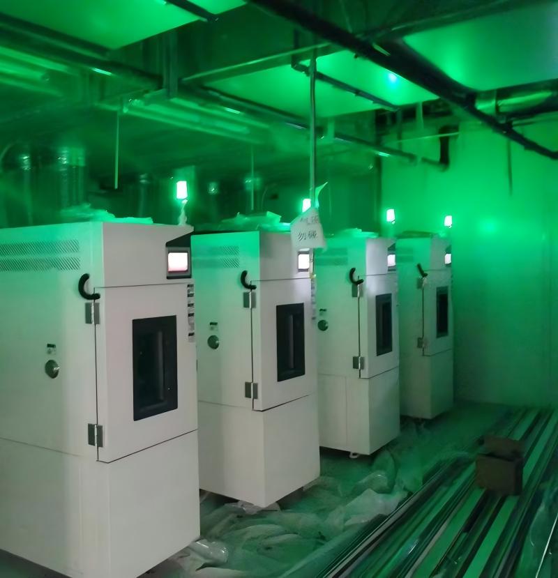
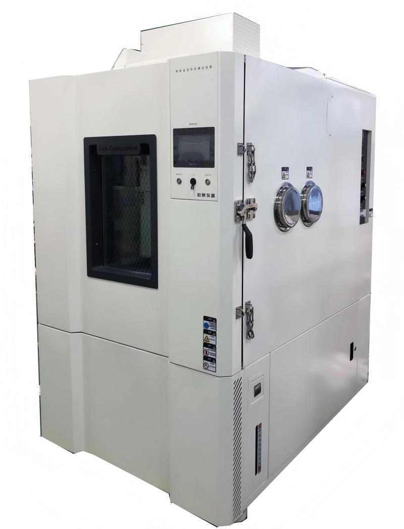
Lighting Installation Position of High and Low Temperature Test Chamber
According to the different needs of users, the installation position of the lamp in the high and low temperature laboratory is different. The constant temperature and humidity test chamber tests the heat resistance, cold resistance, dry resistance and moisture resistance of various materials. Suitable for electronic, electrical, food, vehicle, metal, chemical, building materials and other industries of quality control. This series of products is suitable for aerospace products, information electronic instruments, materials, electrical, electronic products, various electronic components in high and low temperature or temperature and humidity environment, to test its various performance indicators.
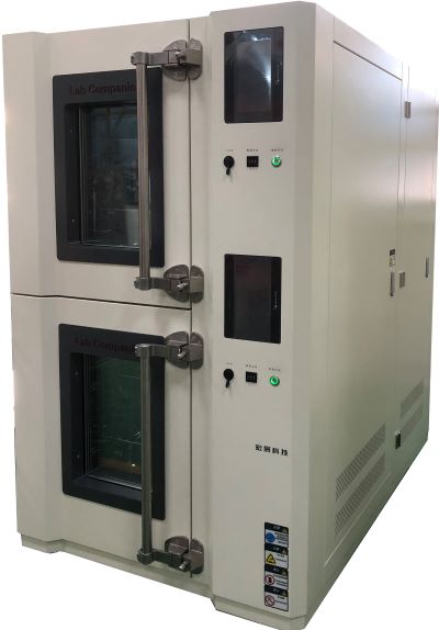
The most common temperature test equipment in environmental test equipment, and similar related products are high and low temperature alternating test chamber, constant temperature and humidity test chamber, high and low temperature and humidity alternating test chamber and so on. It is suitable for high temperature and low temperature reliability test of industrial products. Walk-in high and low temperature test chamber, walk-in high and low temperature test chamber is used for thermal test of national defense industry, aerospace industry, automatic components, automotive parts, electronic and electrical parts, plastics, chemical, pharmaceutical industry and related products. It provides large parts, semi-finished products, and large temperature and humidity test environment space for finished products. It is suitable for the test equipment with large quantity and volume.
Some are installed on the interal chamber or door, and some are not installed. Where is the best place to install light bulbs?
In fact, the high and low temperature test chamber lighting has advantages and disadvantages no matter where it is installed.
If the lighting is installed in the broadcast room, you can clearly see the condition of the entire broadcast room and observe the product at any time.
The lamp is installed on the door, and when the user conducts the double 85 test or the high temperature and high humidity test, the humidity is not easy to invade the lamp, and the lamp is not easy to damage, which can greatly reduce the after-sales service fee. However, its observation field is very small, can only observe the near attractions, customers observe the product is not very convenient.
If the lamp is installed on the right side of the internal chamber, it is recommended to be completely sealed to prevent moisture intrusion to ensure the long-term stable operation of the lamp. If it is installed on a door, it is recommended that the viewing window be trapezoid, so that you can have a wider field of view.
Of course, some corporate customers choose not to install lighting when purchasing high and low temperature test chambers to reduce production costs and later management costs. However, customers can not observe products at any time when doing tests, and they can not meet the needs of different customers who want to observe products.
Sealing Problems and Solutions of High and Low Temperature Test Chamber
High and low temperature test chamber is based on the natural environment such as high temperature, ultra-low temperature, high and low temperature and low temperature drying in the room during the construction of work, and then carries out high and low temperature test and temperature and humidity aging resistance experiment on the commodity, mainly used for industrial products, such as: electronic and electrical, instrumentation equipment, cars and motorcycles, universities and other manufacturing industries.
Because of high temperature testing, ultra-low temperature testing, high and low temperature test cycle system testing, high and low temperature test and other experimental standards, high and low temperature test chamber in the high temperature standards, such as doing 150 ° C extremity of high temperature and 98% of the ambient humidity conditions, and the pressure difference between inside and outside the laboratory to expand substantially, at this moment, the sealing effect of the test chamber really matters. If the airtightness is not very good, it will cause more serious vapor leakage, affecting the precision and accuracy of the temperature.
What are the factors that cause the sealing problem of the high and low temperature test chamber?
First, the constant temperature and humidity test chamber usually has cable holes and ventilation exhaust holes, and the design scheme is very strict.
If the design scheme and production are not scientific, the gap will be too large, and the sealing of the environmental test chamber will not be good. This punching studio should also remember to plug the suitable specifications of the bottle stopper, rubber stopper, etc., to ensure that the sealing of this punching place is intact.
Second, the problem of sealing rubber strips of high and low temperature test chamber. We usually ignore this problem, feel that the sealing strip is added to the door hinge, and should be very sealable under the inhibition of the door hinge, because the aging of the silicone seal, the selection of hard flexibility is unscientific, and the sealing strip is fixed and not the same, often causing steam leakage. It is also simple to handle, often test its tightness, and find that the embrittlement of the sealing strip must be replaced as soon as possible.
Third, because the general volume of the high and low temperature test chamber is relatively large, the tail door specifications are expanded, and the net weight is very large, and the vertical orientation of the door hinge is offset after the long-term load, and the tail door is shifted and closed. Such problems are usually dealt with according to the modified high-load door hinges and the total number of door hinges.
From the above analysis, it can be seen that the sealing problem of the high and low temperature test chamber has some design problems and some maintenance problems. Therefore, we should strictly follow the equipment maintenance manual for regular maintenance in the use of equipment to ensure the normal operation of equipment and no deviation of technical parameters.


 Get A Quote


 IPv6 network supported