Lab Companion 800G CPO Thermal Cycling Test Equipment — Reliable Solution for High-Speed Optical Device Qualification
Jul 30, 2026
1. New Thermal Cycling Test Requirements for Mass 800G CPO Deployment
Driven by the rapid expansion of AI computing power and hyperscale data centers, 800G optical modules have officially entered large-scale commercial deployment. As a next-generation optical interconnection architecture, Co-packaged Optics (CPO) integrates optical engines and switching chips into a single package, delivering outstanding advantages in higher bandwidth density, lower power consumption, and smaller footprint. It has become a core technology trend for 800G and beyond high-speed optical communication systems.
Compared with traditional pluggable optical modules, 800G CPO features ultra-high integration, complex internal structures, and diverse composite materials. During temperature cycling tests, the mismatched thermal expansion coefficients of multi-layer materials easily induce thermal stress, leading to common reliability risks including optical coupling offset, solder joint fatigue, and interface delamination. These challenges raise far stricter standards for thermal cycling accuracy, stability, and test efficiency.
In addition, the fast iteration and mass production of 800G CPO products require high-throughput qualification. Conventional slow temperature cycling equipment can no longer meet the demands of rapid R&D verification and high-volume production testing. Efficient and high-precision thermal cycling test solutions have become essential for global CPO industrialization.
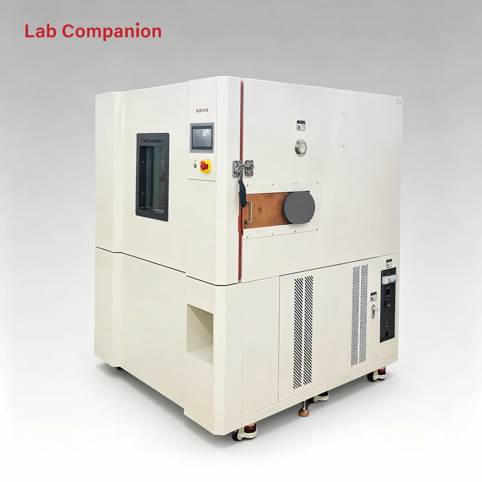
Lab Companion, a professional environmental test equipment brand fromChina, focuses on high-end reliability testing solutions for the optical communication industry. Tailored for 800G CPO qualification requirements, our TH series rapid temperature & humidity chambers, TS series standard temperature chambers, and PS/PL series constant temperature & humidity chambers provide full-process, high-reliability thermal cycling solutions for 800G CPO R&D, validation, and mass production.
2. Core Strengths of Lab Companion 800G CPO Thermal Cycling Test Equipment
Lab Companion’s CPO-dedicated thermal cycling test equipment covers chip-level, module-level, and system-level testing scenarios. It balances high-precision R&D verification and high-efficiency mass production testing, fully complying with international industry standards and meeting the strict qualification requirements of 800G high-speed optoelectronic devices.
2.1 Ultra-Fast Temperature Ramp Rate, Greatly Improve Test Efficiency
Temperature ramp speed determines the overall efficiency of thermal cycling reliability testing. Lab Companion TH series rapid temperature change chambers support a maximum nonlinear temperature ramp rate of15℃/min, enabling fast temperature rise and fall cycles and significantly shortening single-test cycle duration.
For R&D scenarios, ultra-fast thermal cycling effectively accelerates failure exposure, helping engineers quickly identify structural defects, material mismatches, and packaging weaknesses, shorten product iteration cycles, and speed up CPO technology verification. For mass production, high-throughput testing increases batch capacity, reduces unit testing costs, and improves production qualification efficiency.
The equipment supports both linear and nonlinear temperature change modes with adjustable ramp rates. It fully complies with mainstream international standards including IEC 60068-2-14 and MIL-STD-810H, allowing flexible configuration according to different sample specifications and test protocols.
2.2 Wide Temperature Range & High Precision, Ensure Repeatable Test Results
800G CPO devices are highly sensitive to ambient temperature and require extreme temperature resistance verification. Lab Companion thermal cycling chambers offer a wide temperature range of -70℃ to +150℃, fully covering mainstream CPO test conditions such as -40℃~+85℃ and -55℃~+125℃, with sufficient temperature margin for extreme environment qualification.
Equipped with optimized air duct design and high-precision PID temperature control algorithm, the equipment achieves excellent temperature uniformity and stability. The temperature fluctuation is ≤±0.5℃ and temperature uniformity ≤±2℃, eliminating temperature dead zones inside the chamber and ensuring consistent and repeatable test data for high-speed optoelectronic components.
Built-in high-precision temperature sensors and real-time data acquisition system record complete temperature curves throughout the test process. All test data can be exported, traced, and analyzed, supporting standardized test report generation and laboratory quality management.
2.3 Multiple Chamber Sizes & Flexible Configuration, Fit Full-Coverage CPO Testing
With larger overall dimensions and highly integrated structures, 800G CPO modules require larger and more flexible test spaces. Lab Companion provides a full range of chamber volumes from tens of liters to over 1000 liters, adapting to chip, optical engine, CPO module, and complete machine testing requirements.
The large-capacity chamber supports multi-sample simultaneous testing, effectively improving batch test throughput and reducing mass production testing costs. Adjustable multi-layer sample racks allow flexible layout based on sample size and quantity to maximize internal space utilization.
Standard reserved test ports support cable and optical fiber penetration, enabling real-time online monitoring of high-speed optical and electrical signals during temperature cycling. Customized port solutions are also available to meet personalized 800G CPO high-speed signal test demands.
3. Lab Companion Empowers Global 800G CPO Industrialization
As a leading Chinese manufacturer specializing in optical communication reliability testing equipment, Lab Companion has long focused on high-speed optical device qualification. With rich industry experience and mature technical solutions, we have served numerous global optical communication enterprises, supporting the whole process of CPO product development, verification, and mass production.
In the R&D stage, our rapid thermal cycling equipment accelerates reliability verification, helping clients optimize material selection, packaging processes, and structural design, greatly shortening product time-to-market. In mass production, automatic program storage and one-click test operation simplify qualification procedures and improve factory testing efficiency.
Equipped with comprehensive safety protection mechanisms including over-temperature, over-current, and short-circuit protection, the equipment supports stable unattended operation and ensures maximum safety for both test samples and devices.
We provide customized engineering solutions for unique 800G CPO test requirements, including customized sample racks, optimized temperature control procedures, and exclusive data interface configurations, ensuring seamless integration with clients’ existing test systems.
4. Brand Strength & Global Service System
Lab Companion is a premium environmental test equipment brand originating from China, specializing in high-quality reliability testing solutions for optical communication, semiconductor, electronics, aerospace, and automotive industries. Our product portfolio covers temperature & humidity chambers, rapid thermal cycling chambers, thermal shock chambers, and aging test chambers, with stable performance recognized by global clients.
Advanced R&D & Strict Quality ControlBacked by professional R&D teams and independent manufacturing capabilities in China, we continuously optimize core technologies including refrigeration systems, air circulation structures, and intelligent temperature control algorithms. All core components adopt internationally renowned brands. Every unit undergoes strict factory calibration and performance testing to ensure long-term stability, high precision, and durability.
Global Online Technical Support (Overseas Non-On-Site Service)To adapt to global business layout, Lab Companion provides full-lifecycle online technical services for overseas clients. Our professional international support team offers remote equipment installation guidance, operational training, program debugging, routine maintenance guidance, and fault diagnosis. No on-site door-to-door service is provided for overseas orders. Efficient and professional remote support ensures stable and continuous equipment operation for global customers.
5. Conclusion
With the rapid iteration of global 800G CPO technology, high-efficiency, high-precision, and high-stability thermal cycling testing has become an indispensable guarantee for product reliability and mass commercialization.
As a reliable Chinese environmental test equipment brand, Lab Companion 800G CPO dedicated thermal cycling test equipment integrates 15℃/min ultra-fast temperature cycling, -70℃~+150℃ wide temperature range, high-precision temperature control, and flexible multi-scenario adaptation. It fully meets the full-process qualification requirements of 800G CPO from R&D verification to mass production.
Lab Companion will continue to deepen the optical communication testing field, keep pace with global high-speed optical technology upgrades, and provide more professional and efficient reliability test solutions for global customers, boosting the high-quality development of the international 800G CPO industry.
Read More


 Get A Quote


 IPv6 network supported